WEB Interface 49
ID: um_t2gateway CP560 DVB-T2 Gateway User’s Manual Rev. 2.2 (3686)
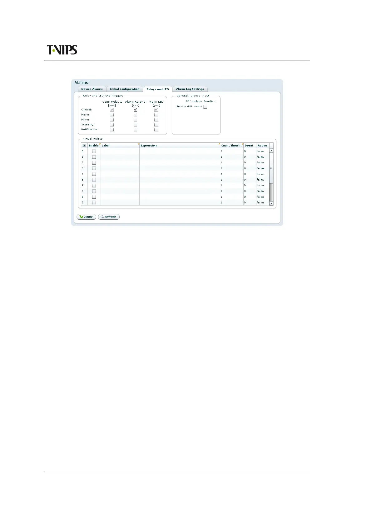
Figure 8.11 Relays and LED configuration
For further details on the physical relays refer to Section B.5.1.
The Virtual Relays field shown in Figure 8.11 also includes settings for the so-called virtual
relays. These are programmable status indicators that can be set to react to any specific alarm
condition. In the simplest case you may want to enable a relay in case a specific alarm ID turns
up. In another case you may want to enable a relay if a specific alarm turns up on a given port.
Each relay status are exported on SNMP. Activation of a virtual relay also generates a specific
alarm, named "Virtual alarm relay activated" (ID=169).
The key element in the settings of the virtual relays is the Expression value. The expression is
very close to SQL in syntax and specifies when the relay should be activated. The behaviour is
as follows for each virtual relay:
1. Each active alarm event is evaluated against the Expression for the virtual relay (if
enabled).
2. If the expression evaluates to true, the Count value is increased by 1. You can at any
time see the current count value. The Count value simply tells you how many of the
current (active) alarm events in the unit that matches the expression.
3. If the count value is larger than or equal (>=) to the Count Thresh. value the relay is
activated.
The expressions are validated before they are accepted by the unit. Table 8.1 shows the field
values you may enter in an expression.