Triggering
3-76
TDS5000 Series User Manual
Overview Control elements and resourcesTo trigger on transition time
Set the
transition time
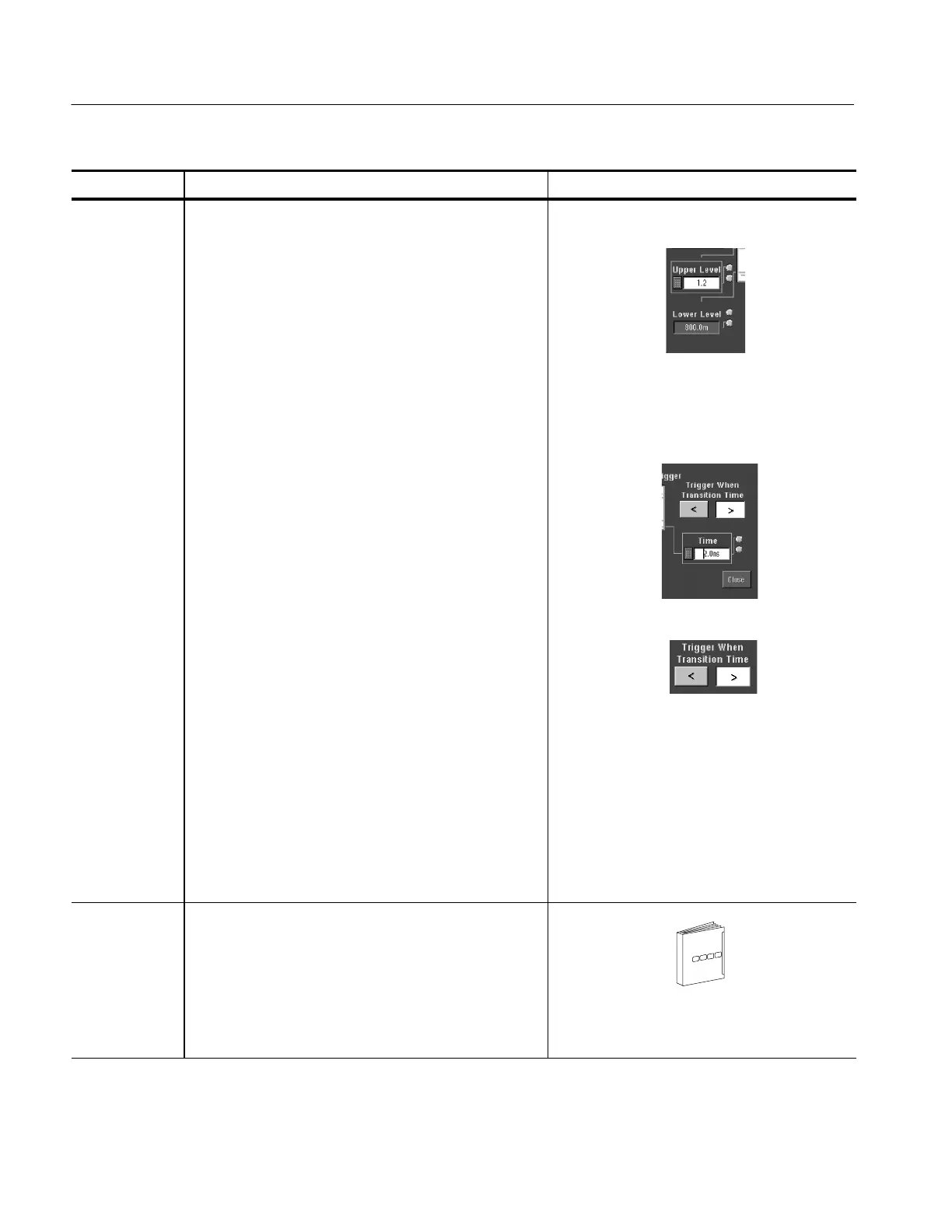
6. The threshold levels and the delt a time setting
determine the transition time (slew rate) setting. The
level settings determine the voltage component of slew
rate (Volts/Second). Click the Upper Level or Lower
Level button and use the mul tipurpose knobs or pop-up
keypad to set the values for the upper and lower levels.
You can set the level(s) to a value appropriate to either
the TTL or ECL logic families by clicking TTL or ECL on
the Level pop-up keypad.
Hint: To use the trigger level marker to set the threshold
levels, open the Display Setup control window, and click
Long on the Objects tab.
7. To finish specifying the slew rate (transition time), set
the time component by clicking Time and using t he
multipurpose knob or keypad to set the delta time value.
8. Click Trigger When Transition Time < to trigger when the
transition time is less than the time you set above. Click
Trigger When Transition Time > to trigger when the
transition time is greater than the time you set above.
If you select Trigger When Transiti on Time > (greater
than) and the oscilloscope does not trigger, the pulse
edge may be too fast. To check the pulse edge speed,
switch to edge triggering. Trigger on the pulse edge and
determine the time the edge takes to travel between the
upper and lower levels that you set for this trigger. The
oscilloscope cannot transition trigger on pulse edges
that traverse between threshold levels i n 600 ps or less.
Also, to reliably trigger on t ransition time, a pulse must
have a width of 7.5 ns or more. A pulse of l ess width
may trigger on the wrong slope or not trigger at all.
Switch to edge triggering and check the pulse width if
you can’t trigger on transition time as expected.
Set mode and
holdoff
9. Mode and holdoff can be set for all standard trigger
types. Refer to Select the trigger mode on page 3--56
and Set holdoff on page 3--59. To learn more about
trigger mode and holdoff, see Trigger Modes on
page 3--51 and Trigger Holdoff on page 3--52.
For mode and holdoff setup, see Select the trigger
mode on page 3--56 and Set holdoff on
page 3--59.
 Loading...

