Incoming Inspection
TDS5000 Series User Manual
1-23
5. Set up the oscilloscope: Push the front-panel AUTOSET button. This sets
the horizontal and vertical scale for a usable display and sets the trigger
source to the channel you are testing.
6. Verify that the channel is operational: Confirm that the following statements
are true.
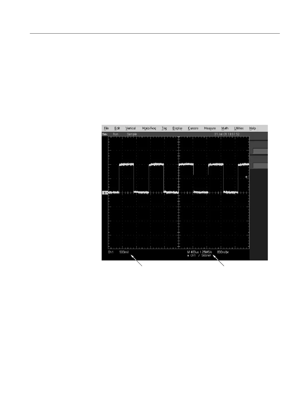
H The vertical scale readout (see Figure 1--6) for the channel under test
shows a setting of 500 mV, and a square-wave probe compensation
signal about 2 divisions in amplitude is on the screen.
Vertical scale readout Horizontal scale readout
Figure 1- 6: Location of vertical and hor izontal scale readouts
H The front-panel VERTICAL POSITION knob for the channel that you
are testing moves the signal up and down on the screen when rotated.
H Turning the VERTICAL SCALE knob counterclockwise for the channel
that you are testing decreases the amplitude of the waveform on the
screen. Turning the knob clockwise increases the amplitude. Returning
the knob to 500 mV returns the amplitude to about 2 divisions.
7. Verify that the channel acquires in all acquisition modes: From the
Horiz/Acq menu, select Horizontal/Acquisition Setup to open the

 Loading...
