Acquiring Waveforms
3-16
TDS5000 Series User Manual
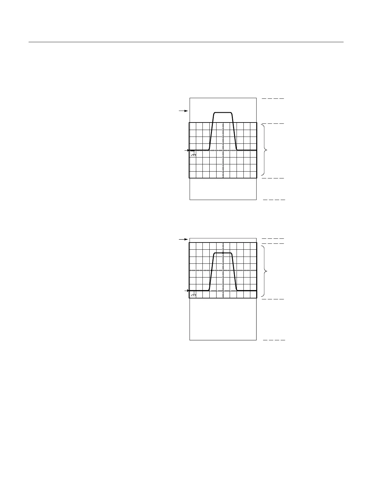
a. SCALE setting det ermines the vertical acquisition window size. This
window is 100 mV/div x 20 divisions (10 graticule divisions and
5 divisions of position)
+0.4 Volt
--0.4 Volt
b. Vertical position can change the location of the display graticule within the
acquisition window, repositioning it so that its waveform appears in the
graticule
Vertical window
Channel reference
indicator
Graticule
+0.7 Volt
--0.1 Volt
Vertical window
Channel reference
Indicator
Graticule
+1.0 Volt
--1.0 Volt
+1.0 Volt
--1.0 Volt
1
1
Figure 3- 3: Setting vertical range and position of input channels
The vertical offset control affects the vertical acquisition window and the
displayed waveform as follows:
H The vertical range (window) is always centered around the offset value. The
range is the voltage level at the middle of the vertical acquisition window.
With no (zero) offset, as shown in Figures 3--3 a and b, that voltage level is
zero (ground).

 Loading...
