2-8
TDS5000 Series User Manual
System Overview Maps
The following sections provide a high-level description of how the oscilloscope
acquires, processes, and outputs signal information.
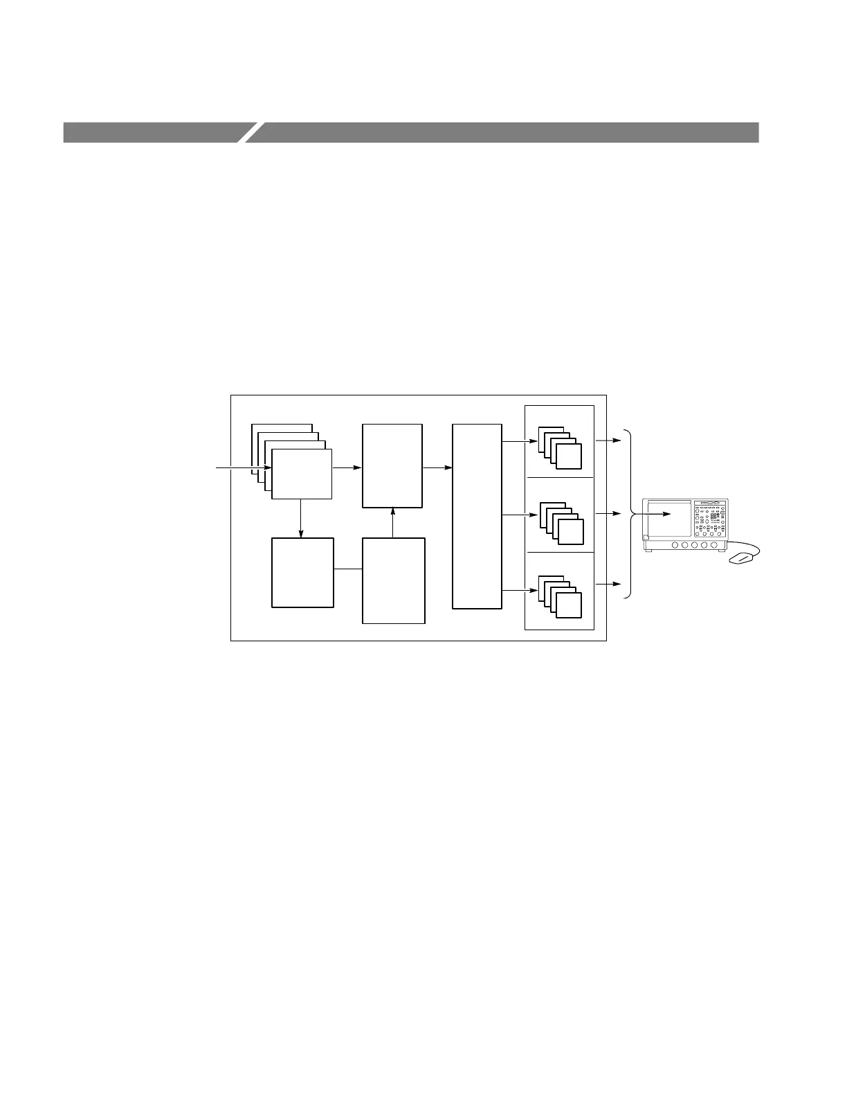
Functional Model Map
Input channels
Time base
system
CH 1--4
CH1. . .CH4
Math 1--4
Acquisition
system
DSP
Output and
Storage
Digital Signal Acquisition
Amplitude
scaling
page 3--14
page 3--21
pages
3--115,
3--135
pages
3--100,
3--135
Trigger
system
page 3--49
Ref 1--4
Display and UI
Signal P rocessing and
Transformation
Page 3--99
The oscilloscope has four high-level subsystems or processes (consisting of both
hardware and software functions) and the “data” that connects them:
H Digital Signal Acquisition System. Acquires a waveform record from each
signal you probe using the following subsystems:
H Input Channels. Conditions the input signal, primarily through the use
of analog hardware, before converting the signal to digital form.
H Trigger System. Recognizes a specific event of interest on the input signal
and informs the Time base system of the occurrence of the trigger event.

 Loading...
