Appendix A: Specifications
TDS5000 Series User Manual
A-5
Specification Tables
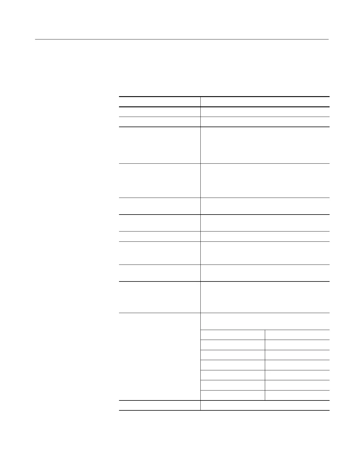
Table A- 2: Channel input and vert ical specifications
Characteristic Description
Input coupling DC, AC, and GND
Input channels Two or four, all identical
Input impedance, DC coupled 1MΩ ± 1.0% in parallel with 18 pF ±2pF
50 Ω ±2.5% ;
VSWR ≤ 1.6:1 from DC to 500 MHz
(TDS5052/TDS5054),
VSWR ≤ 1.5:1 from DC to 1 GHz (TDS5104)
Maximum voltage at input BNC
(1 MΩ)
150 V
RMS
CAT I, and ≤ 400 peak
For steady state sinusoidal waveforms, derate at
20 dB/decade above 200 kHz to 9 V
RMS
at 3 MHz and
above
Maximum voltage at input BNC
(50 Ω)
5V
RMS
, ±30 V peak
Differentia l delay at input BNC ≤ 100 ps between any two channel s with the same scale
and coupling settings
Deskew range, typical ±75 ns
Channel-to-channel crosstalk ≥ 100:1 at 100 MHz, and ≥ 30:1 at the rated bandwidth
for any two channels with the same scale and coupling
settings
Digitizers 8-bit resolution, separate digitizers for each channel
sample simultaneously
Sensitivity range 1MΩ: 1 mV/ div to 10 V/div, in a 1-2-5 sequence
50 Ω: 1 mV/div to 1 V/div, in a 1-2-5 sequence
Fine adjustment available with ≤1% resolution
Analog bandwidth DC 50 Ω coupling, bandwidth limit set to Full, operating
ambient ≤30 °C, derated by 2.5 MHz/°C above 30 °C
TDS5052/TDS5054
SCALE range
Bandwidth
1 mV/div to 1.99 mV/div DC to 175 MHz
2 mV/div to 4.98 mV/div DC to 300 MHz
5mV/divto1V/div DC to 500 MHz
TDS5104 SCALE range Bandwidth
1 mV/div to 1.99 mV/div DC to 175 MHz
2mV/divto1V/div DC to 1 GHz
Analog bandwidth limit, typical Selectable between 20 MHz, 150 MHz, or Full

 Loading...
