SDI7 module removal and replacement
4. Loosely instal
l the six T10 TORX screws that attach the Main circuit board to
the chassis.
CAUTION. To prevent damage to the circuit boards and to the FPGA, do not
tighten these screws at this time.
5. If necessary, position the outer rear panel over the BNC connectors.
6. Install the three P1 Posidriv flathead screws, from the bottom through the
chassis into the heat sink. Torque these screws to 5.0 in/lb.
7. Replace the washers and
9
/
16
inch nuts onto the BNC connectors. Torque
these nuts to 14.0 in/lb.
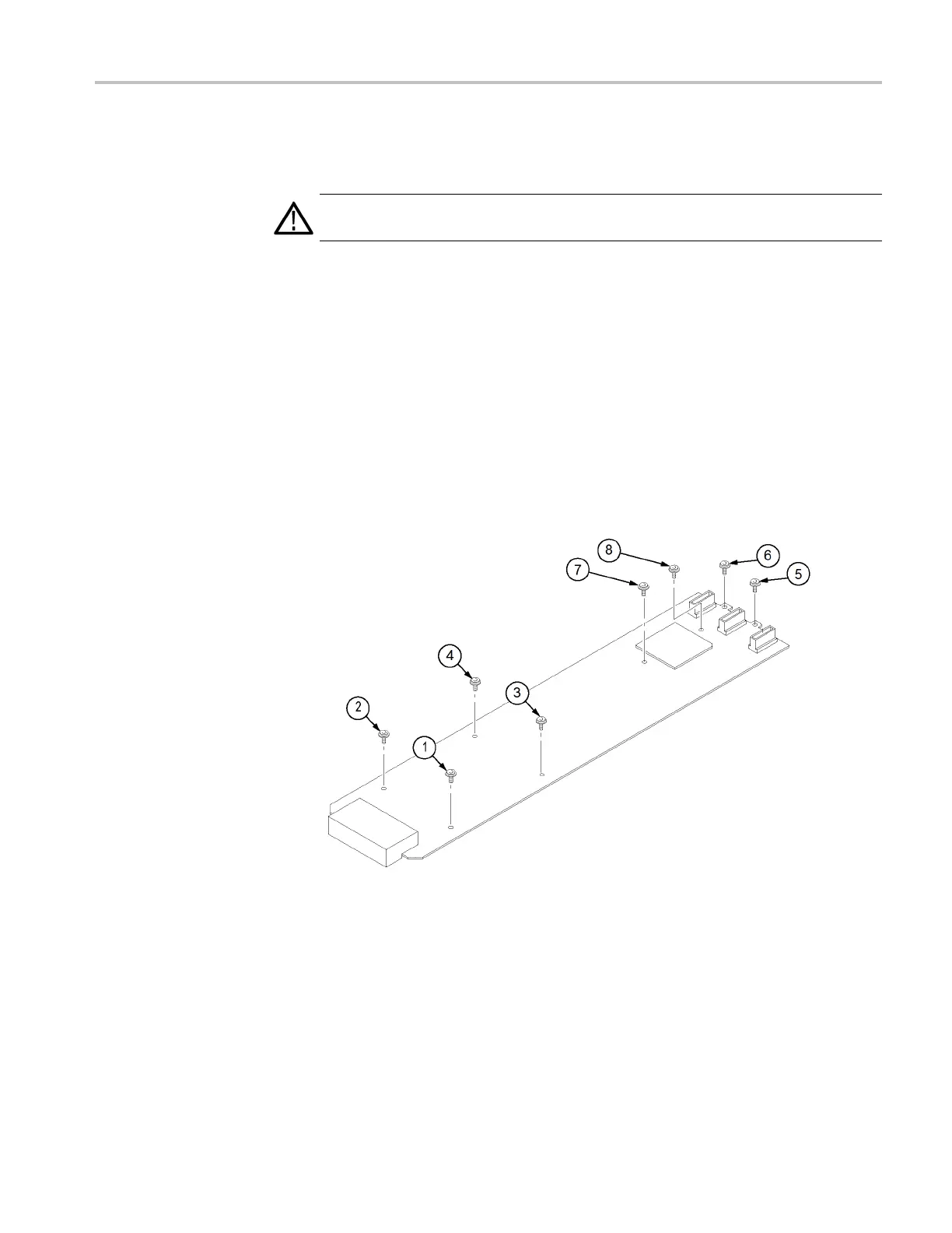
8. Tighten the eight T10 screws that attach the Main circuit board to the chassis
and to the heat sink, in the sequence shown below. (See Figure 14-3.) Note
that the two screws that attach the Main board to the heat s ink are tightened
last (7 and 8). Torque al l these screws to 8.0 in/lb.
Figure 14-3: SDI7 module main board installation
The SDI7 module is now ready to install in the mainframe.
TG8000 Multiformat Test Signal Generator Service Manual 14–29

 Loading...


