HYDRAULICS
8E-28
Inspection
1. Inspect special bolts (1) for damaged threads or
seal ring.
2. Inspect commutator ring (6) and commutator (5)
for cracks or burrs.
3. Inspect rotor set (7 and 8) for nicks, scoring, or
galling on surfaces or for broken or worn splines.
4. Place the rotor set on a window glass. Inspect the
rotor lobe and roller vane clearance on both sides
(Figure 8E-10). If there is more than 0.005”
(.13 mm) clearance, replace motor.
Figure 8E-10. Rotor Lobe Inspection
5. Inspect drive link (10) for cracked or worn splines.
6. Inspect thrust bearings (11) and (15) for wear,
brinelling, corrosion, and missing rollers.
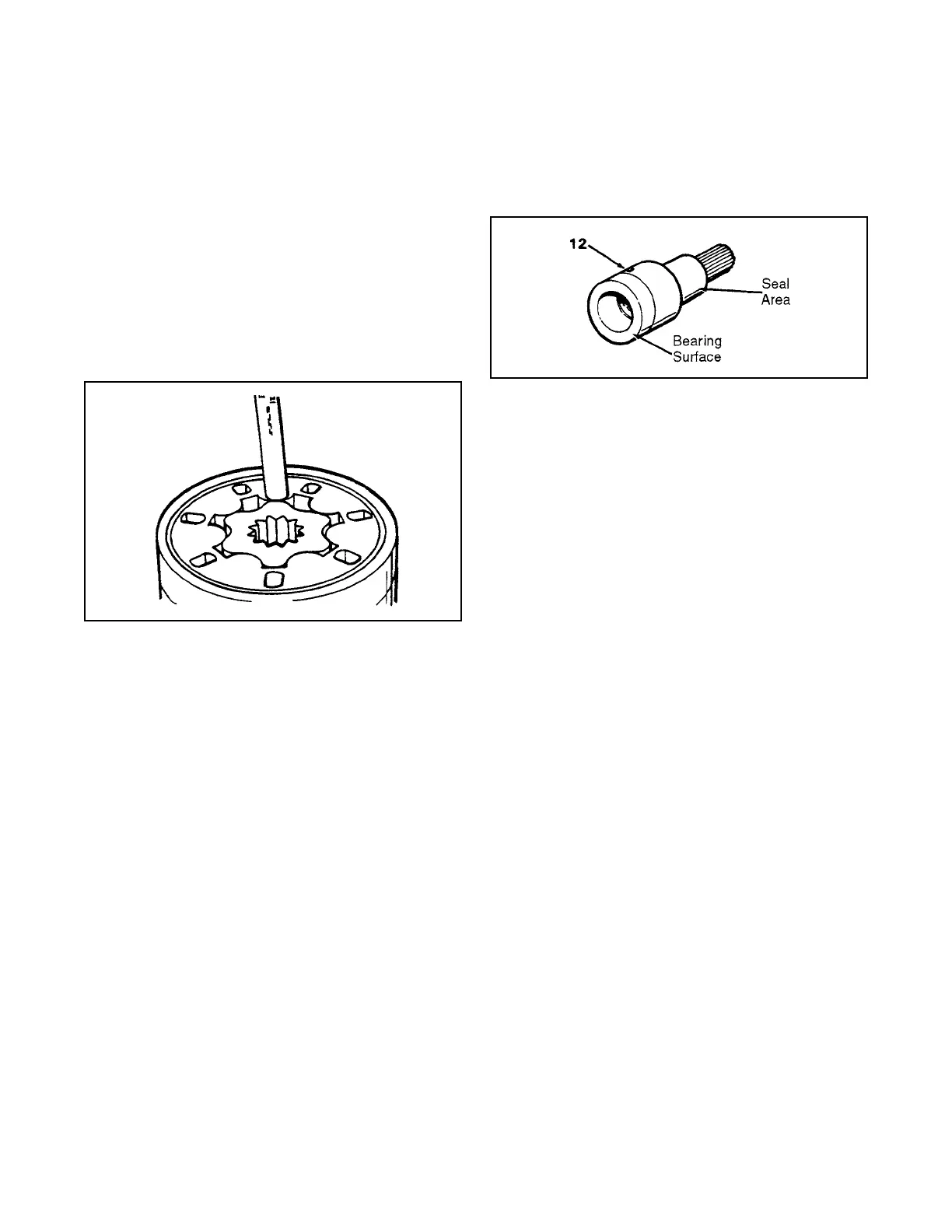
7. Inspect coupling shaft (12, Figure 8E-11), bearing
and seal area for galling, nicks, grooves, severe
wear, or corrosion and discoloration (heat).
Inspect for damaged or worn internal and external
splines or keyway.
Figure 8E-11. Coupling Shaft Inspection
8. Inspect housing (18) for cracks, nicks, burrs,
brinelling, or corrosion of machined surfaces.
Remove burrs; do not damage surface. Inspect
tapered holes for thread damage.
9. If bearing (13) was not removed, check the bear-
ing for broken or worn parts, also for missing
rollers.
Reassembly
1. The following reassembly steps (Figure 8E-12
through Figure 8E-17) include the installation of
bearings. If bearings were not serviced, omit
Steps 1, 2, 5, and 6.
2. When reassembling make sure scribed marks line
up (see Figure 8E-5).
 Loading...


