5-58 4252490-Rev A
HYDROSTATIC POWER TRAIN
5
NOTE
Record the location of fittings before removing to ensure
correct installation.
8. Remove, inspect, and replace fittings (7 and 8) from
left wheel motor (9) as necessary.
9. Remove, inspect, and replace fittings (10 and 12)
from right wheel motor (11) as necessary.
Installation Notes
• Install front wheel motor by reversing the order of
removal.
• Tighten front wheel motor mounting screws (3) to
59–66 lb-ft (80–90 N·m).
• Tighten case drain port fitting (12) to 27 lb-ft (37
N·m).
• Tighten inlet and outlet port fittings (7, 8, and 10) to
77 lb-ft (105 N·m).
• Pressure filter the traction system upon start-up if
metal debris is found in system oil or motor. (See
“Portable In-Line Filter” on page 5-5.)
• Check hydraulic oil level. Add oil as needed. (Refer
to “Parts and Maintenance Manual” for correct oil
specifications.)
Rear Wheel Motor
See Figures 5-61 and 5-62.
1. Park the mower safely. (See “Park Mower Safely” on
page 1-6.)
2. Remove rear wheel. (See “Rear Wheel—3WD Units”
on page 9-25.)
3. Remove rear wheel hub. (See “Rear Wheel Hub—
3WD Units” on page 9-26.)
Figure 5-61
NOTES
• Label all hydraulic hoses and tubes before
disconnecting to ensure correct installation.
• Close all openings with caps or plugs to prevent
contamination.
4. Disconnect hoses (1 and 2).
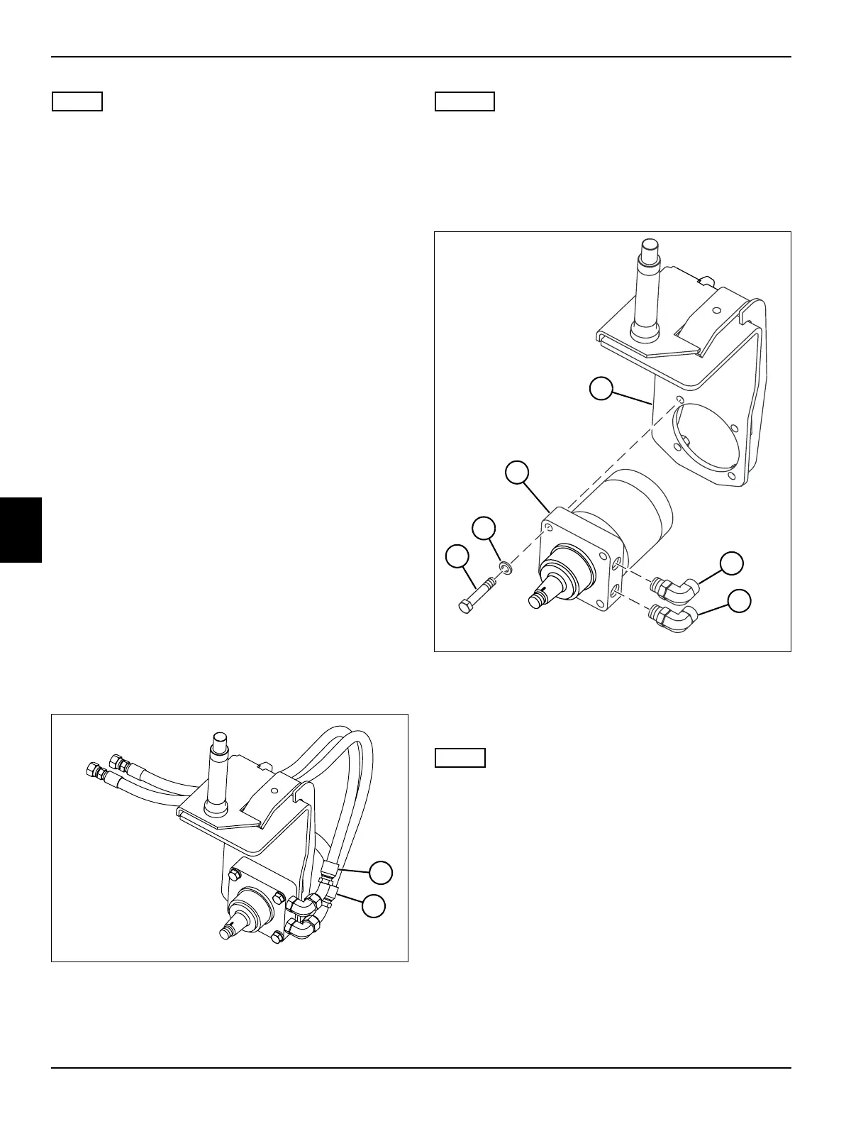
Figure 5-62
5. Support rear wheel motor (8) and remove four
mounting screws (6) and lock washers (7).
6. Remove rear wheel motor (8) from fork weldment (3).
NOTE
Record the location of fittings before removing to ensure
correct installation.
7. Remove, inspect, and replace fittings (4 and 5) as
necessary.
TN3878
1
2
TN3879
8
7
6
4
5
3

 Loading...


