CUTTING UNITS
4252490-Rev A 8-25
8
NOTE
Record the locations of flat washers (7) to ensure correct
installation.
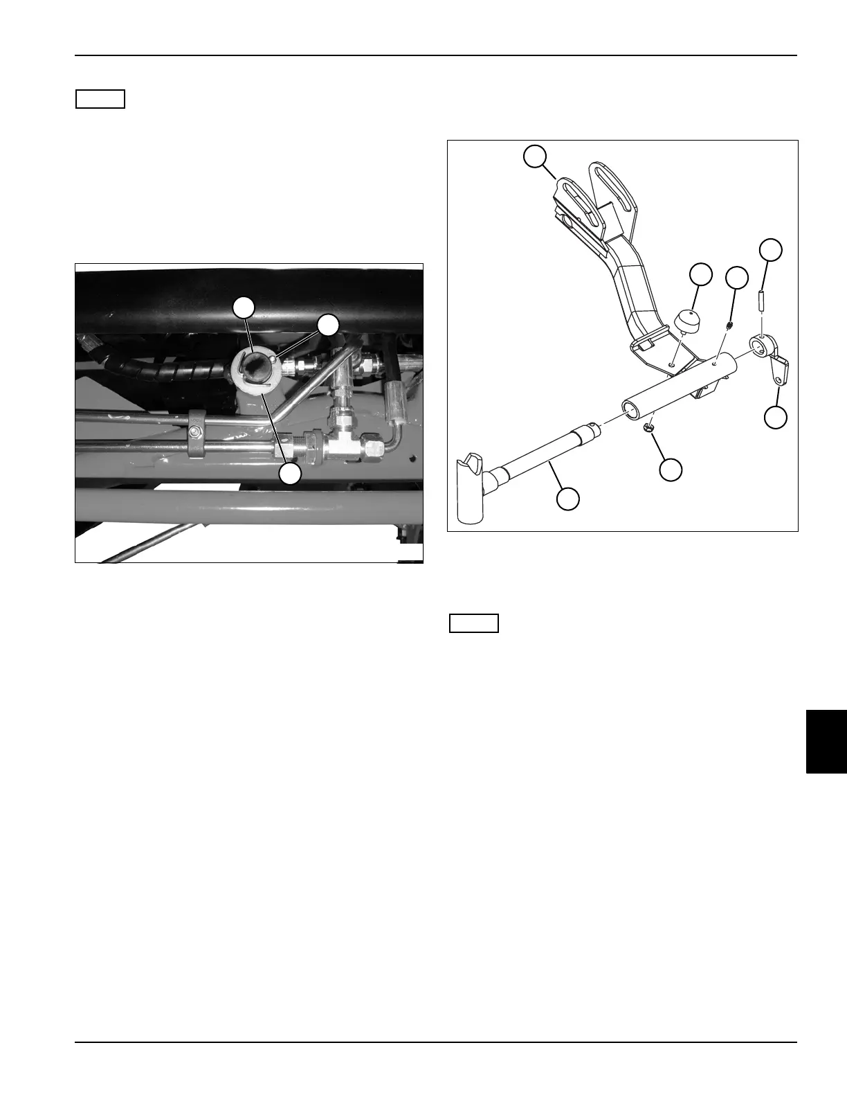
4. Remove cotter pin (6), pin (5), and six flat washers
(7) from lift cylinder (8) and lift arm (13).
5. Remove cotter pin (11), pin (12), and two flat
washers (10) from lift cylinder (8) and frame (9).
6. Move lift cylinder (8) aside.
Figure 8-23
7. Remove cotter pin (15) and flat washer (16) from lift
arm shaft (14).
8. Remove lift arm.
Disassembly and Assembly
See Figure 8-24.
Figure 8-24
NOTE
Apply grease that meets or exceeds NLGI Grade 2 LB
specifications to grease fitting (3).
TN3739
14
15
16
1 Lift Arm 5 Link Arm
2 Rubber Bumper 6 Nut
3 Grease Fitting 7 Pivot Shaft
TN3741
6
5
2
1
3
4
7

 Loading...


