Station Wiring Diagrams
DK40 Universal Slot PCB Wiring
Strata DK40 I&M Manual Spring 1999
4-5
Refer to the Strata DK40 Programming Manual or DK Library CD-Rom for more details.
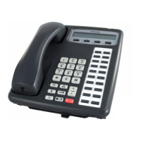
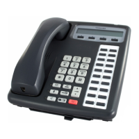
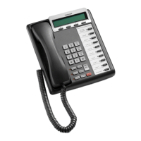
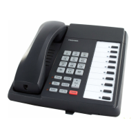
Electronic Station Wiring Diagrams
Figure 4-4 MDF Wiring/Electronic Telephone to PEKU
Notes
• To receive OCA, the 6500-series electronic
telephone must have an HVSU2 or the combined
HVSI and HVSU installed.
• Program 31, button/LED 03 must be ON for
electronic telephone to receive OCA.
• An HHEU must be installed inside 6500-series
electronic telephones for headset or HESB, Loud
Ringing Bell option.
1578
Electronic Telephone
Circuit 2
Circuit 3
Circuit 4
Circuit 5
Circuit 6
Circuit 7
Circuit 8
Not Used
Circuit 5
Circuit 6
Circuit 7
Circuit 8
OCA T1 (OA)
OCA R1 (OB)
Modular
Cord
Only if Electronic Telephone
Receives "Off-Hook" Calls
25-Pair Cable w/Male amp Connector
1
2
3
4
5
6
7
8
9
10
11
12
13
14
15
16
17
18
19
20
21
22
23
24
25
26
27
28
29
30
31
32
33
34
35
36
37
38
39
40
41
42
43
44
45
46
47
48
49
50
1
2
3
4
5
6
7
8
9
10
11
12
13
14
15
16
17
18
19
20
21
22
23
24
25
26
27
28
29
30
31
32
33
34
35
36
37
38
39
40
41
42
43
44
45
46
47
48
49
50
W-BL
BL-W
W-O
O-W
W-GN
GN-W
W-BR
BR-W
W-S
S-W
R-BL
BL-R
R-O
O-R
R-GN
GN-R
R-BR
BR-R
R-S
S-R
BK-BL
BL-BK
BK-O
O-BK
BK-GN
GN-BK
BK-BR
BR-BK
BK-S
S-BK
Y-BL
BL-Y
Y-O
O-Y
Y-GN
GN-Y
Y-BR
BR-Y
Y-S
S-Y
V-BL
BL-V
V-O
O-V
V-GN
GN-V
V-BR
BR-V
V-S
S-V
26
1
27
2
28
3
29
4
30
5
31
6
32
7
33
8
34
9
35
10
36
11
37
12
38
13
39
14
40
15
41
16
42
17
43
18
44
19
45
20
46
21
47
22
48
23
49
24
50
25
VA
VB
DA
DB
VA
VB
DA
DB
VA
VB
DA
DB
VA
VB
DA
DB
VA
VB
DA
DB
VA
VB
DA
DB
VA
VB
DA
DB
OA
OB
OA
OB
OA
OB
OA
OB
OA
OB
OA
OB
OA
OB
KRONE
237A
To PEKU
w/Female
Connector
Circuit 2
Circuit 3
Circuit 4
Voice A1 (VA)
Voice B1 (VB)
Data A1 (DA)
Data B1 (DB)
Jacketed Twisted Pairs
CW1308 0.5mm
Station
Station Cabling
OCAT
OCAR
654321
123456
BS6312

 Loading...

