Power Failure Emergency Transfer Option
DK40 Installation
Strata DK40 I&M Manual Spring 1999
2-19
Refer to the Strata DK40 Programming Manual or DK Library CD-Rom for more details.
Power Failure Emergency Transfer Option
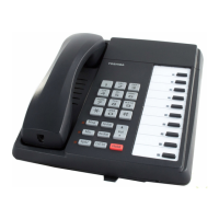
To enable this option, a dedicated standard telephone must be connected to the Power Failure
Transfer Interface (PF1) of a DK40 Base KSU equipped with a TCOU.
Note
During normal operation, this telephone cannot be used and does not count as a
station (does not reduce the number of system’s available stations).
If there is a power failure, the telephone automatically is connected to Exchange Line 1.
When power is restored, the system resumes normal station and Exchange line assignments,
and the dedicated telephone becomes inoperative again.
Important!
This is not available on a DK40 system with a TBSU installed.
Installing Power Failure Emergency Transfer
➤ Connect a standard telephone to the PF1 connector in the Base KSU
(see Figure 2-13).
Testing Power Failure Emergency Transfer
1. Turn the system power switch OFF.
2. Lift the emergency standard telephone handset, and verify that there is Exchange line
dial tone.
4
3
5
2
Screw Terminal
CO1 (Base KSU)
MDF
Exchange
Line
Screw Terminal
PF1 (Base KSU)
A
B
MDF
PFT
Standard
Telephone
DK40 TCOU
A
B
Power Fail
Connection
Power Available
Connection
DK40
TCOU
Exchange
Line 1
2155
Figure 2-13 Base KSU Power Failure Transfer (PFT) Circuit Diagram

 Loading...

