TR-Electronic GmbH 2016, All Rights Reserved Printed in the Federal Republic of Germany
Page 32 of 153 TR-EMO-BA-GB-0022 v03 09/29/2020
5.1.1 Operating condition
S1:
Not ready to switch ON
The drive is in the initialization phase.
Drive initialization ended.
The output stage cannot be switched on.
The output stage can be switched on.
Drive parameters can be changed.
Output stage switched on.
The drive can be used in accordance with
the set operating mode:
see as from chapter “DSP 402 drive
profile” page 30
The drive performs a quick stop. If the
Quick stop option code object
0x605A = 5, the drive then remains in this
state.
S7:
Fault reaction active
There is an error. The relevant
troubleshooting is carried out.
Troubleshooting is complete.
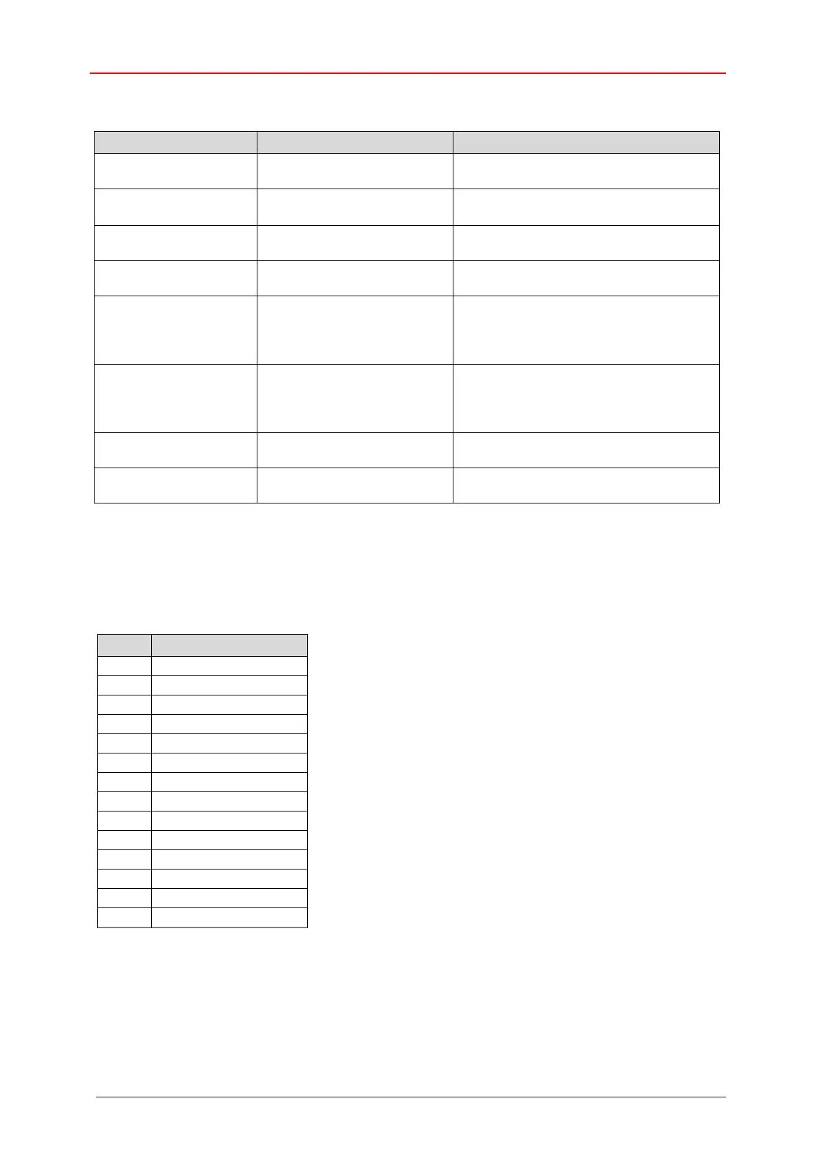
Table 4: States of the status word
x: not relevant bits
The operating condition is shown by means of appropriate bit pattern in the status word 0x6041. The
bits in the status word are defined as follows:
Description of the mode of operation-specific bits,
see following chapters:
- “Profile Position (PP)” operating mode, p 35
- “Profile Velocity (PV)” operating mode, p 40
- “Homing (HM)” operating mode, p 44
- “Cyclic Synchronous Position (CSP)” operating mode, p 47
- “Cyclic Synchronous Velocity (CSV)” operating mode, p 50
- “Cyclic Synchronous Torque (CST)” operating mode, p 53
Table 5: Operating states, status word