8 Stakeout Workflow
The software computes the elevation of the reference line at that point, and projects the designated
cut and/or fill side slope magnitudes from that reference point, through your position, along a line
referred to as the slope indicator. The slope indicator line is shown in the map view, extending from
the reference line to the currently predicted catch point location. In predicting the location of the
catch point, if you have defined both cut and fill slope magnitudes, the software determines
whether the cut slope or fill slope is applicable at the reference point.
When staking building pad side slopes, the building pad has both internal and external right-angled
corners. If you are staking external corner points, then the software automatically calculates the
side slope as projected radially from the corner point. At an internal corner, the software calculates
the catch point at a bisectional angle.
The Catch point option enables you to stake out points where the side slope intersects the ground
surface as it is found to exist. As you stake catch points at fixed intervals, you should adapt to the
existing terrain and be aware of the effect that it may have on the location of the daylight line. You
can freely switch between the Stake at fixed intervals mode and Stake at randomly chosen interval
modes.
The Line option enables you to stake out the side slope’s reference line. The software guides you to
the line at the nearest point to where you currently are, or to a specific station. The Side Slope
option enables you to place a grade stake at any required location on the side slope between the
reference line and the catch point. You can toggle between the different stakeout methods using
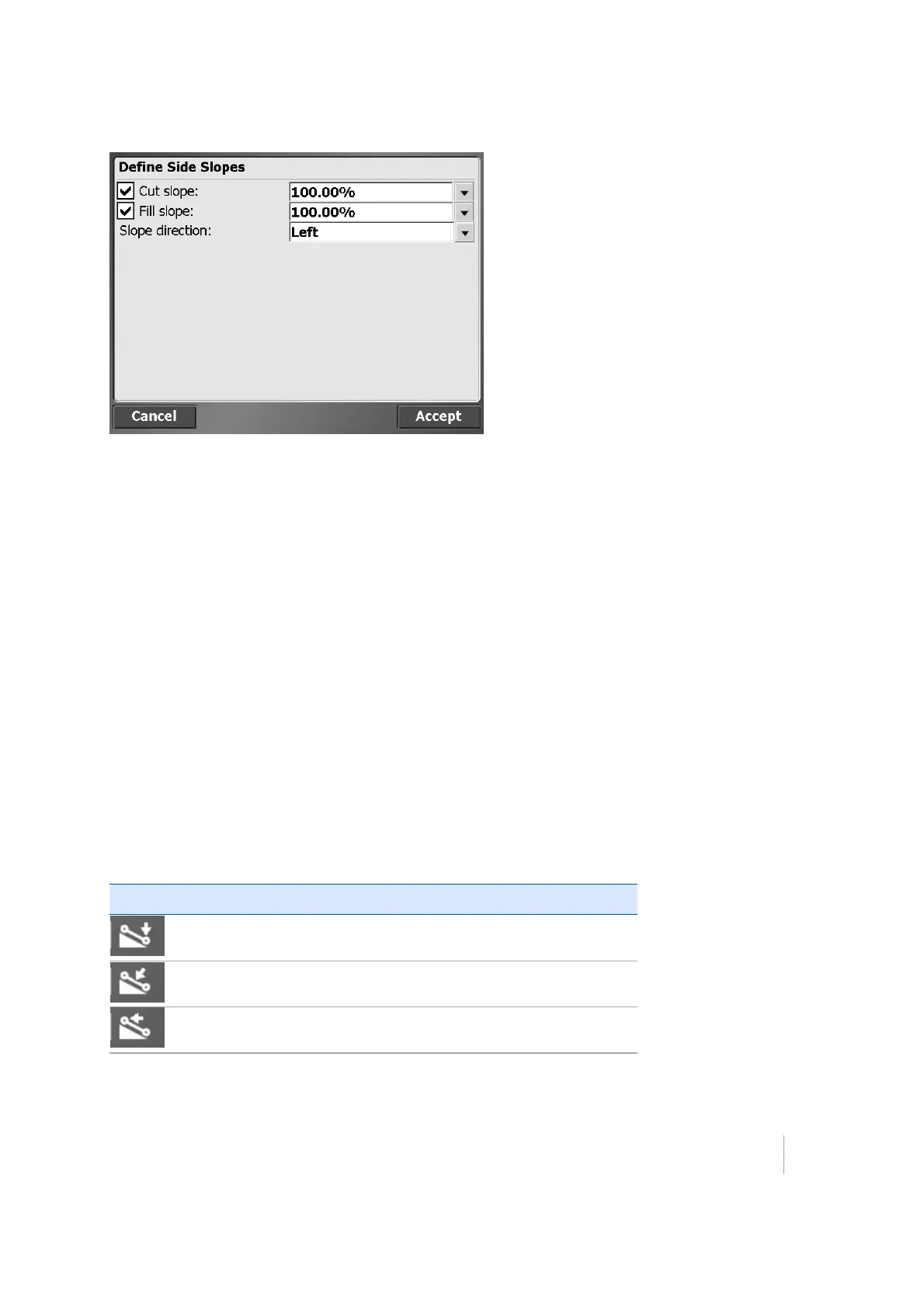
the button at the right of the status bar. Tap on the icon on the right of the status bar:
Icon Description
Stake catch point
Stake side slope
Stake line
Trimble SCS900 Site Controller Software User Guide 71