Motion Coordinator Technical Reference Manual
Trio BASIC Commands 8-23
Motion and Axis Commands
Example 4:
CAMBOX Pattern Mode
Setting bit 3 (value 8) of the link options parameter enables the CAMBOX pattern
mode. This mode enables a sequence of scale values to be cycled automatically.
This is normally combined with the automatic repeat mode, so the options parame-
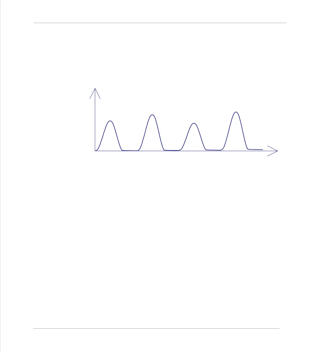
ter should be set to 12. This diagram shows a typical repeating pattern which can
be automated with the CAMBOX pattern mode:
The parameters for this mode are treated differently to the standard
CAMBOX
func-
tion
CAMBOX(start, end, control block pointer, link dist, link axis,
options)
The start and end parameters specify the basic shape profile ONLY. The pattern
sequence is specified in a separate section of the
TABLE
memory. There is a new
TABLE
block defined: The “Control Block”. This block of seven TABLE values defines
the pattern position, repeat controls etc. The block is fixed at 7 values long.
Therefore in this mode only there are 3 independently positioned
TABLE blocks
used to define the required motion:
Axis 0 Speed
SHAPE BLOCK
This is directly pointed to by the CAMBOX command as in any
CAMBOX.
 Loading...