Motion Coordinator Technical Reference Manual
Hardware Overview 2-5
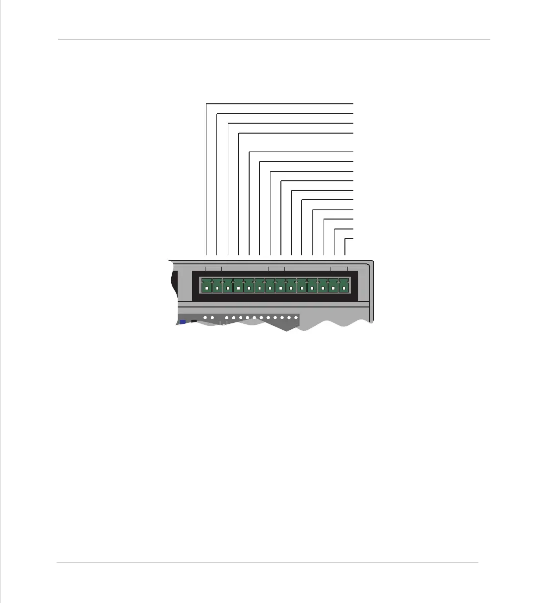
Motion Coordinator MC202
Top 14 Way Connector:
This is a 14 way 3.81 pitch connector. The connector provides for the +/-10volt
analog output, the enable relay contacts, and the I/O connections.
Analog Output
This feature when required is used to drive a servo drive or inverter connected to
axis 0. The +/-10 volt analog output is isolated from the power input and the I/O
modules of the MC202 and is powered via an internal DC-DC converter. The pair
of connections should be connected by a screened cable to the drive input.
The drive enable pins are used to interlock the MC202 with a servo OR stepper
drive and should be used in all cases. The connections are internally connected
to a pair of normally open relay contacts which close when the drive is enabled.
I/O Power Inputs
The I/O 0 Volts and I/O 24 Volts are used to power the 24 volt inputs and outputs.
The I/O connections are isolated from the module power inputs on the 5-way
CAN connector. The I/O 0 Volts connection must be made if any inputs or outputs
are used. The I/O 24 Volts is only required to power outputs and may be omitted
if none are used. The I/O channels 8 to 11 are bi-directional and can be used
012389101124v0vV+V-
I/O Channel 10
I/O Channel 11
I/O Channel 9
I/O Channel 8
Input 3
I/O 24 Volts
I/O 0 Volts
Input 2
Input 1 / Registration Axis 1
Input 0 / Registration Axis 0
Amplifier Enable B
Amplifier Enable A
Vout +
Vout -