CFM-BL10Pro General instruction manual
11 / 87
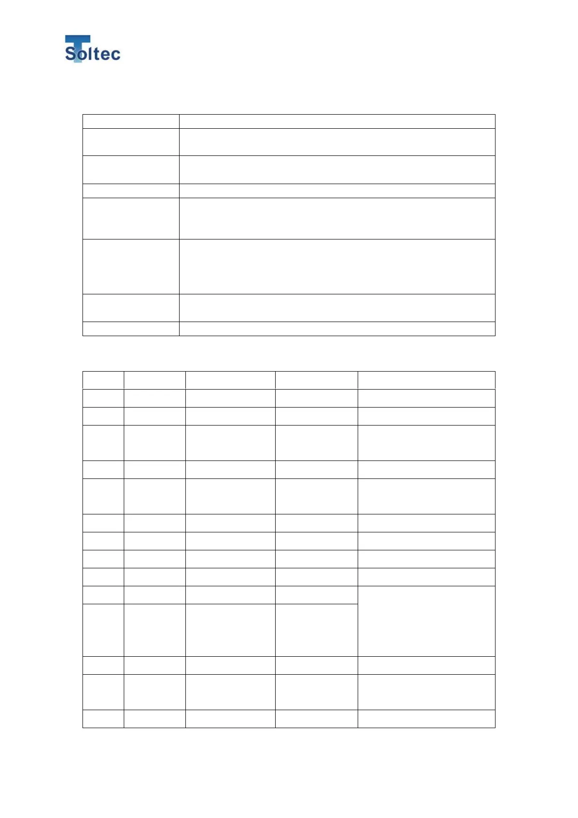
1.3. Specifications
L 182mm x W 119mm x H 50mm
Resolution: 12bit
Max sampling rate: 20kHz
Refer to 1.4. I/O pin assignment.
1) PC Communication (USB2.0)
2) USB data memory (Applicable connecting USB: FTA32 Max
capacity 32GB)
AC adaptor model: SPU16A-108 from SINPRO
(Input: 90 ~ 264V, Output: 24V, 0.62A)
Do not use any other power supply or adapter because these are
out of warranty.
0 ~ 40℃, 90%RH or lower with no dew.
CFM-BL10Pro is compliant with the RoHS directive.
1.4. I/O pin assignment
Externally reset Error mode.
Externally turn to Teach mode.
Externally start and end Bypass
mode.
Externally operate Program number.
Start capturing force curves with
Trigger SW mode.
Externally operate Program number.
Maximum 100 part numbers can
used. As for the details, refer to
7.2.5 External Program selection.
Power supply for an external trigger
sensor.