CFM-BL10Pro General instruction manual
75 / 87
7.2.3. Machine connection (Eject signal)
Separately from STOP signal, CFM has a judgement result signal which Is called
EJECT signal. This signal is available when a press machine can receive good or
bad judgement result signals. And Eject signal is output only for crimp judgement
result. The signal is output as a pulse wave. After a terminal is crimped, the signal
is output within 0.1 seconds.
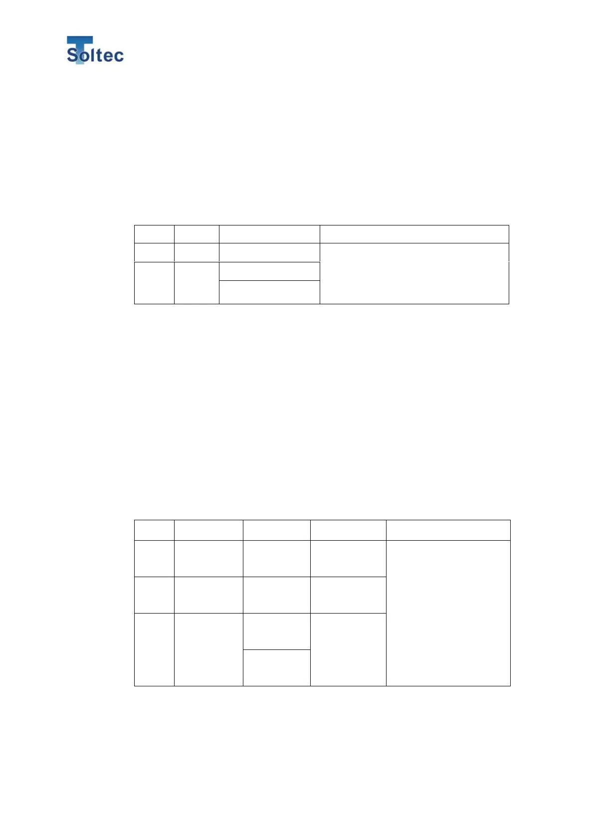
When judgement results are good or
bad, you can select a pulse output time
among 50, 100, 150, 200ms and Level
in System setting. GND is common with
Pin No. 24 and 25. Either is fine.
<Notice>
- Eject is output via a photocoupler
- Connect the above two signals to machine Input and GND.
7.2.4. External trigger switch installation (Option)
With an optional trigger switch, sync a timing of start capturing force curves to one
of press machine crimping. Select trigger type from “Fall” which means CFM
detect the point where the trigger signal turns from OFF to ON or “Rise” which
means CFM detects the point where the trigger signal turns from ON to OFF.
Example: Our recommended sensor - Omron E2E-S type
Wire color of
trigger switch
When we supply the
trigger switch, a
connector is attached to
the trigger switch cable.
Connect it to the
connector attached I/O
cable.