CFM-BL10Pro General instruction manual
73 / 87
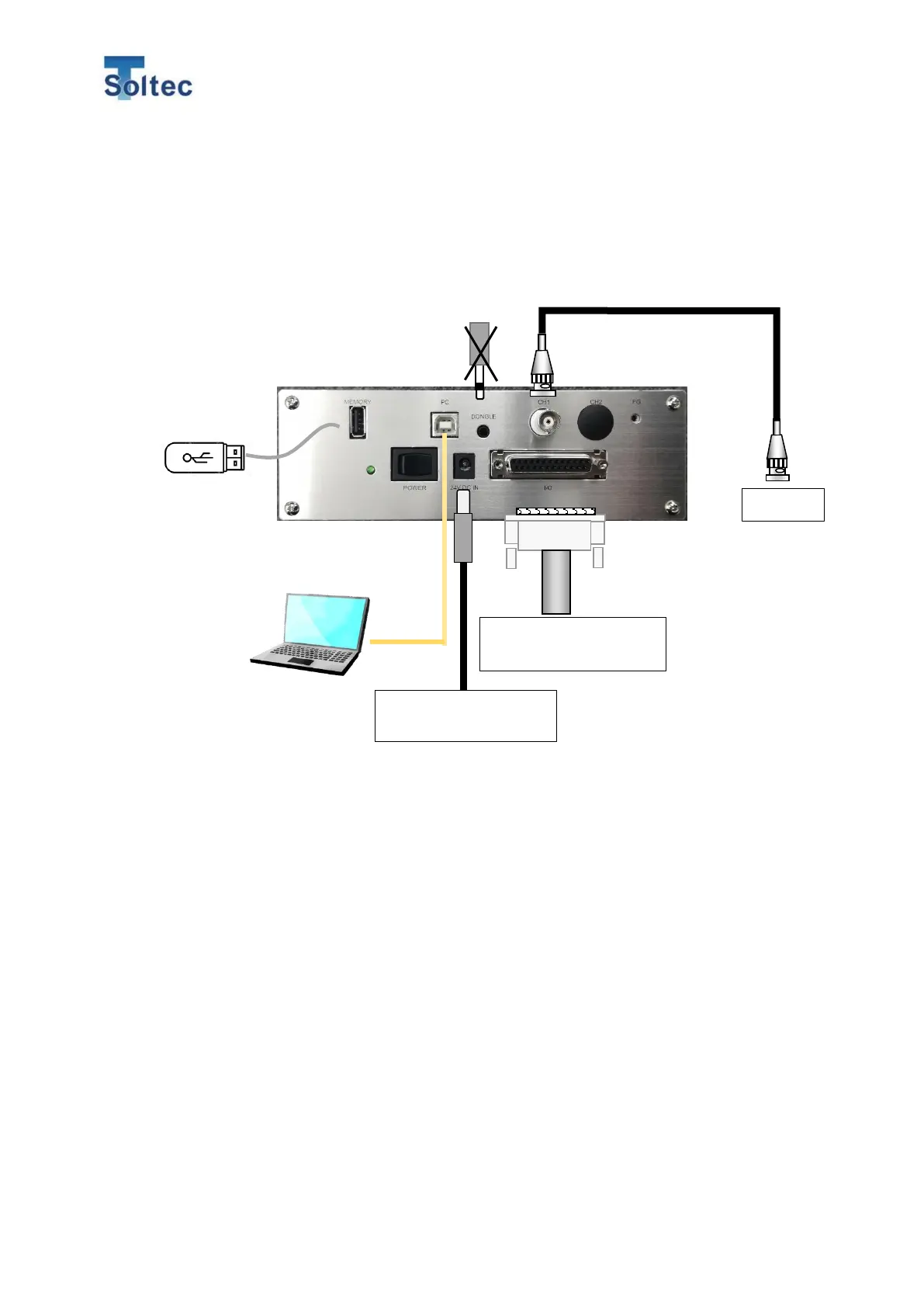
7.2. Connection and wiring
7.2.1. Main unit connection
Connect cables and external devise according to the figure below. When you
connect sensor and IO cables, turn off CFM.
<Notice>
・ Connecting and fixing each cable so as not to put stress on the cable.
・ Because the cable is easily affected on external electric noise, do not lay it in
parallel to a high voltage power cable.
・ To avoid putting stress on each connector, lay the cable with moderate flexibility.
Machine I/O and
External trigger switch
USB cable
Connect USB A-B type cable.
The cable is not included.
BNC cable
Connect attached 1.5m cable.
I/O cable
Connect attached 1.5m cable.
Dongle key
*Not available for this unit
USB memory
Save all crimp data
until the memory
reaches its capacity.
*USB memory is not
included.
PC software
With PC software, monitoring
force curves, operation, setting
and saving data can be possible.