CFM-BL10Pro General instruction manual
74 / 87
7.2.2. Machine connection (STOP signal)
CFM outputs STOP signal (non-voltage contact / Level output) as a Machine
interlock, when an error occurs.
If a machine does not have a port for STOP signal, cut foot switch cables and
connect STOP signal cable with them.
STOP signal is output within 0.1 second after crimping.
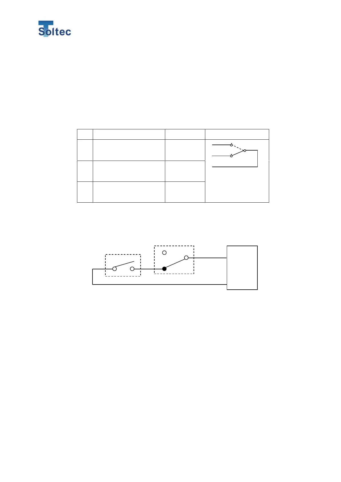
Normally open (Albeit
contact)
Normally close (Break
contact)
*The above tables show the state when the main unit is turned on.
< Connection Example >
In the case of the above example, when an error is detected, relay contact is
reversed. Then you cannot crimp next samples until the error mode is reset.
When CFM is in Parameter mode or turned off, the relay contact is reversed, and
the machine cannot start crimping.
<Caution>
・ The rated current of the relay is “AC125V 0.5A、DC24V 1A”. Do not apply the
current over the above specification.
・ Do not use CFM STOP relay as a switch of a coil side of another relay.