CFM-BL10Pro General instruction manual
46 / 87
2. Screen description
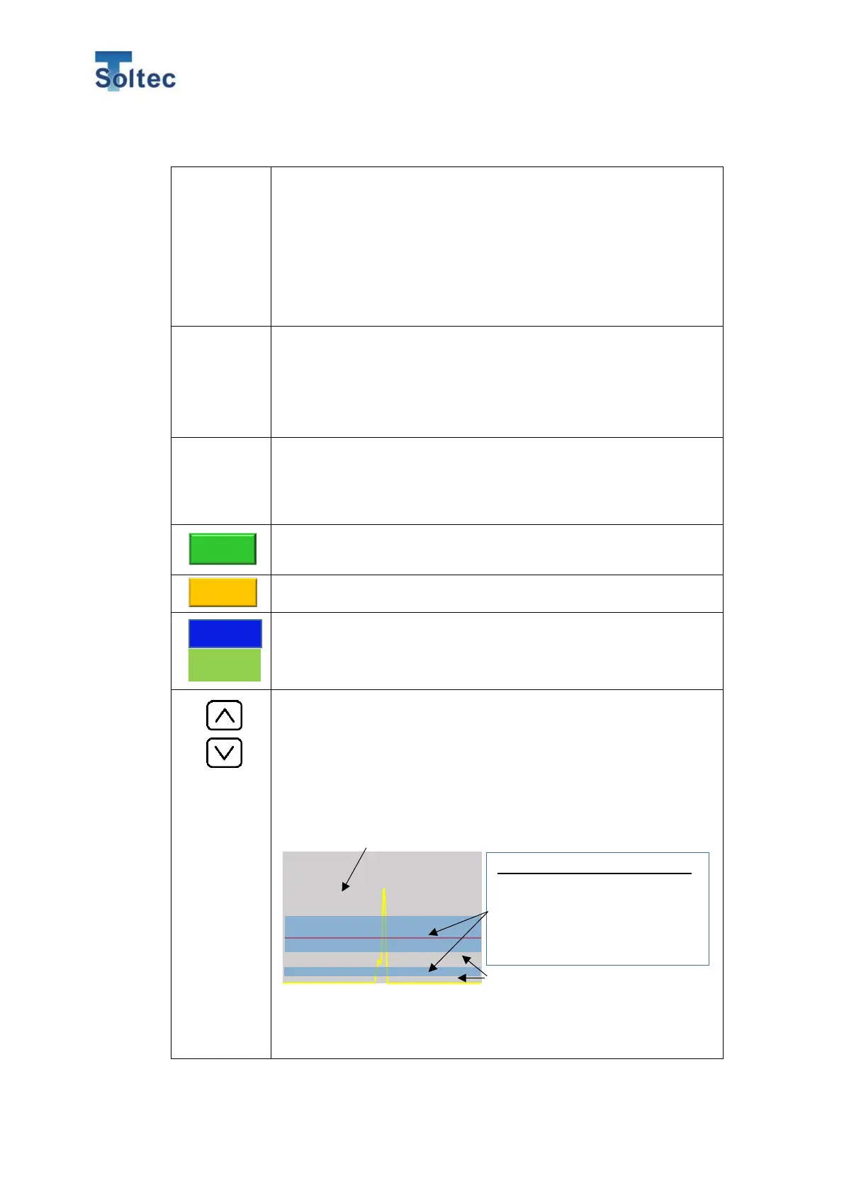
The sensor signal that is input in the above No.4, is shown as a
force curve. The X axis of the graph is the selected force curve
capturing time. Because the scale of X axis changes depending
on the capturing time, the width of the force curve also changes
depending on the capturing time as well.
*You may see an inputted force curve in yellow line as one vertical
line when you select 5 sec in the capturing time because the
inputted curve is very short.
Threshold
line in red
line
This red line is the Trigger level that is automatically decided by
CFM in Auto trigger mode. In trigger mode, CFM judges a force
curve that is over the line. (CFM start capturing force curve when
a sensor signal is over a noise level.) In switch fall and rise mode,
this line has no effect on capturing a force curve because an
external trigger sensor decides the capturing point.
Pulse signal
in blue line
This blue line is the signal from an external trigger sensor in
Switch fall and rise. When Switch fall/rise and Manu meas are
selected, CFM starts capturing force curve at the first edge of this
pulse signal.
The force curve capturing time can be selected.
Press button to switch 1 sec to 5 sec.
Press this button and CFM starts capturing a force curve.
Crimping has to be done within the selected capturing time.
CFM shows the Trigger level in red line as a voltage.
Its range is 20 to 1000. The initial setting is 40.
These are button for adjusting the threshold voltage of Trigger
level but normally you do not need to adjust by manually.
*Pay attention to the point below when you adjust the Trigger
level.
An appropriate position of the Trigger level for displayed yellow
force curve is roughly the blue area below.
Appropriate range for the Trigger level.
CFM might not be able to detect big
defective samples such as no strands
crimp, if the Trigger level is high. In this
case, adjust the Trigger level at the
The top of the force curve or above the peak of the force curve, is not suitable for
the point of the Trigger level. With that point, CFM cannot recognize a force curve.
It is difficult for CFM to capture a correct
and stable force curve at this area.
Therefore, this area is not suitable for
setting the Trigger level at this area.