Vertiv™ | Liebert® STS2/PDU
™
User Manual | Rev. 6 | 10/2017 119
14.2.8 Color Graphical Display
The display is located in the front of the unit. Front panel display is an LCD touchscreen display for monitoring
and configuring the unit. See Figure 56 for a drawing of the touchscreen display.
14.2.9 RS-232 Port
The unit is equipped with an RS-232 port for connecting a terminal or PC. See Figure 54 for the port’s location.
See 12.1 - Using the RS-232 Port for instructions on using a PC terminal with the unit.
14.2.10 Terminal Port Connections
The system has an asynchronous serial port configured as Data Terminal Equipment for terminal access only
(half duplex). The CPU services the terminal port with no handshaking. The serial port conforms to RS-232 levels
with a data format of 9600 Baud, 1 start bit, 8 data bits and no parity bits. The serial port is 1000VDC isolated
(non-SELV) and ESD protected to 15kV air discharge.
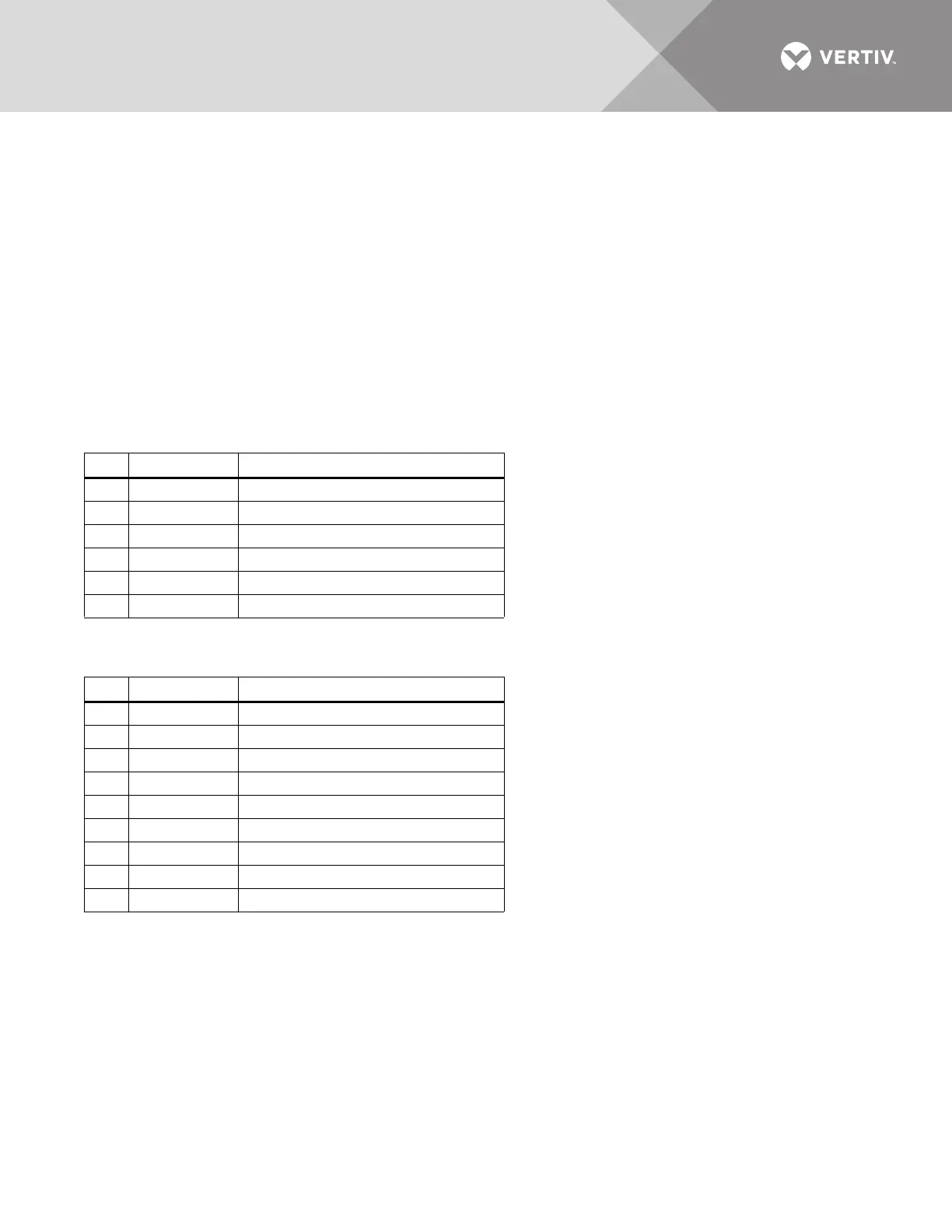
The connector is a 6 Pin MTA plug with connections shown below.
A DB9 male connector is added and connected parallel to the 6 position header. It is configured as DTE.
Table 27 MTA plug pin-out
Pin
Signal Name Function / Comments
1 ISO_GND Isolated service terminal ground
2 ISO_TXD Isolated service terminal transmit output
3 ISO_RXD Isolated service terminal receive input
4 NC No Connection
5 NC No Connection
6 NC No Connection
Table 28 DB9 pinout
Pin
Signal Name Function / Comments
1 NC No Connection
2 ISO_RXD Isolated service terminal transmit output
3 ISO_TXD Isolated service terminal receive input
4 NC No Connection
5 ISO_GND Isolated service terminal ground
6 NC No Connection
7 NC No Connection
8 NC No Connection
9 NC No Connection