Vertiv™ | Liebert® STS2/PDU
™
User Manual | Rev. 6 | 10/2017 18
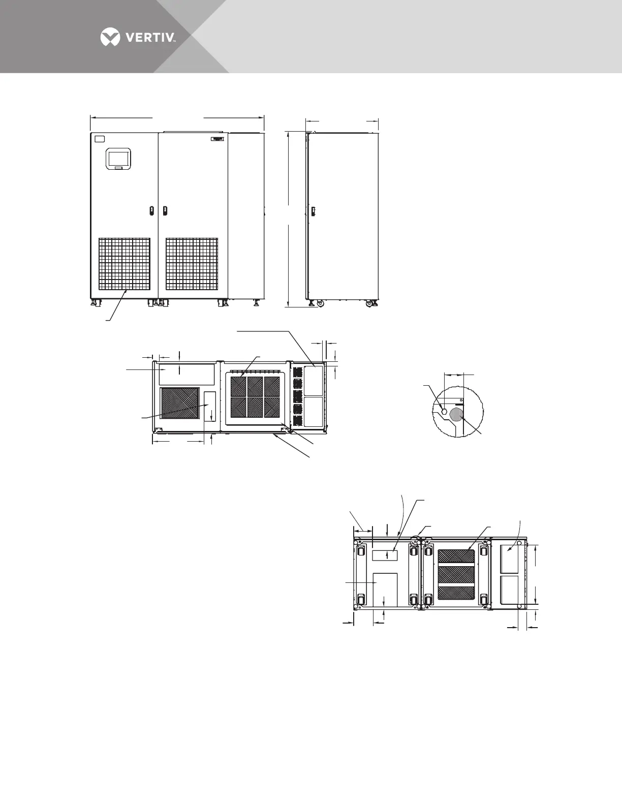
Figure 8 Outline drawing, 250A Liebert STS2/PDU with right side I-Line distribution
PSP11206
Rev. 2
1.1"
(27.9mm)
2.8" (71mm)
Air
Intake
Bottom Input Power
Conduit Entry
Area 14.8" x 10.4"
(376 x 264mm)
Bottom Output
Conduit Entry Area
(2) 12.5" x 7.2"
(318 x 183mm)
Top Output
Conduit Entry Area
(2) 13.1" x 7.9"
(333 x 201mm)
ir Intake Area
Do not block air
filter, typical
See Detail A
Top Input Power
Conduit Entry Area
24.4" x 9.4"
(620 x 239mm)
2.75"
(69.8mm)
Typical
Stabilizing
Foot
1.18" (457mm) clearance above unit required for air exhaust
2. Installation and service access required in front only.
3. Heat output: Approx. 11,737 BTU/hr (3.44kW).
4. Approximate weight: 3993 lb. (1815 kg).
5. Unit bottom is structurally adequate for forklift handling.
6. Keep cabinet within 15 degrees of vertical while handling.
7. Color: IBM off-white
8. Open door to replace air filter, disposable type, size: 1" x 25" x 25"
(25 x 635 x 635mm).
9. Threaded mounting holes (see Detail A) are provided for seismic
anchoring or floor stand. Mounting bolts must be threaded into unit mounting
holes from underneath unit base. If a floor stand is used, the casters must rest
on the floor stand to support the unit’s weight.
10. Top and bottom cable entry available through removable
access plates. Remove, punch to suit conduit size and replace.
12mm Diameter
Threaded Mounting
Hole; 4 typically
See Note 9
Hinged Access Panel
To Input Breakers
120° Front Door Swing
All doors with
lift-off hinges
Top Control Conduit
Entry Area 12.8" x 5.1"
(325 x 130mm)
Bottom Control
Conduit Entry
Area 11" x 4.6"
(279.4 x 116.8mm)
Front
8.4"
(214mm)
26"
(660mm)
8.8"
(224mm)
4"
(101.6mm)
2.6" (66mm)
5.6"
(142.2mm)
5.8"
(147mm)
TOP
RIGHT SIDE
FRONT
BOTTOM
Detail A
(Front of Unit
Shown without Side Panel)
1.1"
(28mm)
32.3" (820mm)
76.8 (1950mm)
77.6
(1970mm)
Air Exhaust
1.8" (46mm)
2.3"
(58mm)