PSP11020
Rev. 0
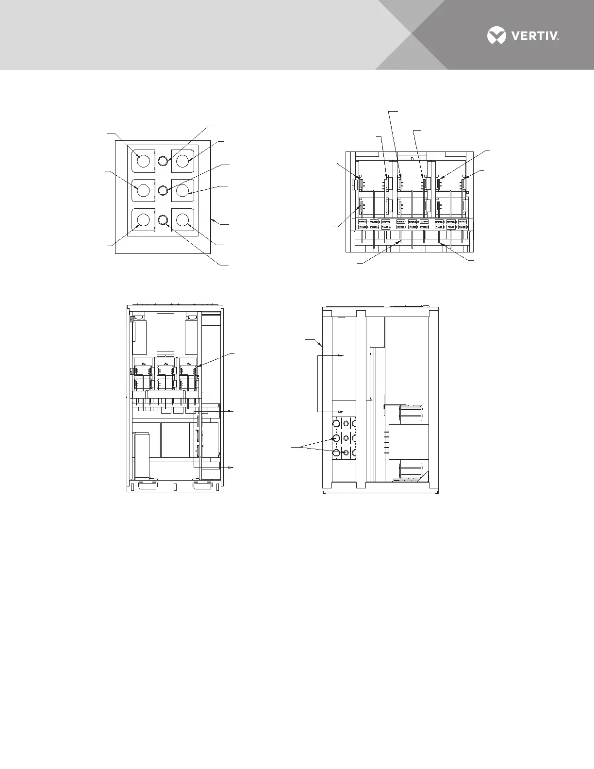
FRONT
STS Section
Accent Panels Not Shown
W21A,B,C, & D to
Source 1 Phase A
W22A,B,C, & D to
Source 1 Phase B
W23A,B,C, & D to
Source 1 Phase C
Unit Front
W27A,B,C & D to
Output Phase A
W24A,B,C, & D to
Source 2 Phase A
W25,A,B,C, & D to
Source 2 Phase B
W29A,B,C, & D to
Output Phase C
W26A,B,C, & D to
Source 2 Phase C
W28A,B,C, & D to
Output Phase B
RIGHT SIDE
STS Section
Accent Panels Not Shown
Notes
1. Take labeled wires from breaker section (cabinet
not shown) through CTs and through-holes as shown
in Section D - D of STS cabinet. Attach wires to
busbars in STS cabinet. See Section E - E for details.
2. See drawing PSP11018 for breaker section of cabinet.
D
Section
D - D
Section
E - E
D
E
E
CTs and
Through-Holes
Typical
See Section D-D
SECTION D - D
Move wire groups from breaker cabinet
through above section of STS2 cabinet.
SECTION E - E
With fuse bracket removed
attach wires to the
corresponding busbars
SEE
SECTION
E - E
Source 2 Phase A
W24A,B,C & D
Output Phase A
W27A,B,C & D
Output Phase B
W28A,B,C & D
Source 2 Phase B
W25,A,B,C & D
Output Phase C
W29A,B,C & D
Source 2 Phase C
W26A,B,C, & D
Source 1 Phase A
W21A,B,C, & D
Source 1 Phase B
W22A,B,C, & D
Source 1 Phase C
W23A,B,C & D
FRONT