Vertiv™ | Liebert® STS2/PDU
™
User Manual | Rev. 6 | 10/2017 76
10.1 Normal System Turn-On
1. Depending on the type of distribution used:
• If equipped with output breaker CB8, open CB8.
• If equipped with output inline panelboards, open panelboard main breakers CB8 and CB9 and, if supplied, CB10 and
CB11.
• If optional subfeed breakers are supplied, open subfeed breakers CB12 and CB13.
See Figures 3 through 6 for location of breakers.
a. Retract the bolts on the key interlocks for CB1 and CB2.
b. Extend the bolts on the key interlocks for CB4 and CB5, thus preventing CB4 or CB5 from being turned ON.
2. Apply source/input power to both Liebert STS2/PDU inputs by closing CB6 and CB7.
The touchscreen control panel should become active and operate properly when at least one of the inputs is energized.
3. Verify that nominal input voltages are applied to both inputs (Source 1 and Source 2).
The input voltages, selected preferred source, breaker and switch status and alarms are indicated on the Mimic screen.
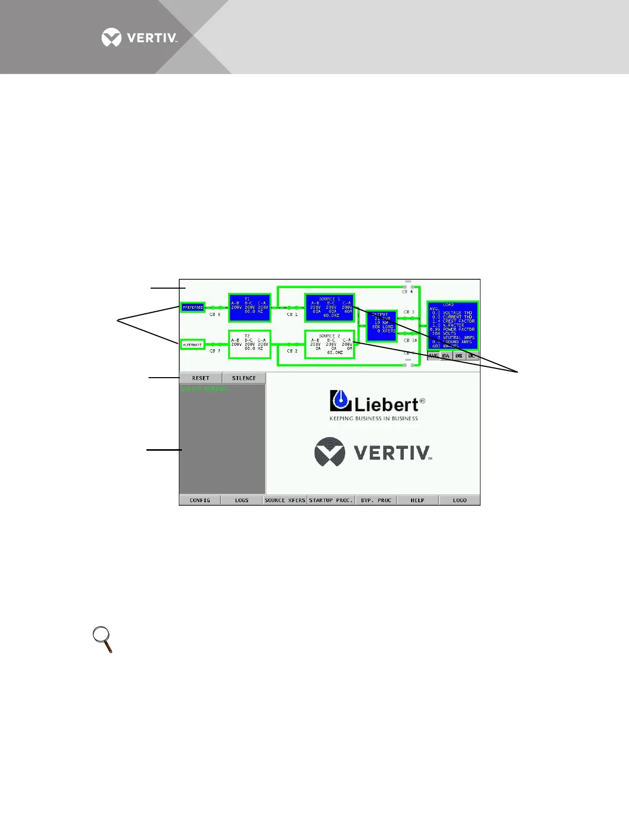
Figure 58 Liebert STS2/PDU touchscreen
4. Close CB1.
5. Verify that Source 1 voltages are nominal and that CB1 breaker status is correctly indicated on the Monitor/Mimic screen.
6. Close CB2.
7. Verify that Source 2 voltages are nominal and that CB2 breaker status is correctly indicated on the Mimic screen.
8. Verify that boxes for the preferred source and corresponding Liebert STS2/PDU are highlighted on the Mimic screen,
indicating which side of the Liebert STS2/PDU is on.
9. Close Output Breaker CB3 (for redundant output configurations, also close CB3A).
10. Verify that CB3, the Output box and the Load box are highlighted, indicating that CB3 is closed and the STS output is
energized. On units with I-line panelboard, the panelboard is also energized.
11. Press the RESET button on the touchscreen to reset any previous alarms.
12. Check the Event Display and the Mimic to verify there are no active alarms. If any active alarms are displayed, refer to 11.0 -
Alarms and Faults for a description of the alarms and possible causes. Correct all active alarm conditions before
proceeding.
13. If unit is equipped with output breaker CB8, close CB8. The output and load are energized.
14. If unit is equipped with output inline panelboards, close panelboard main breakers CB8 and CB9 and, if supplied, CB10 and
CB11. Turn on panelboard breakers. If optional subfeed breakers are supplied, close subfeed breakers CB12 and CB13.
15. Turn on the load equipment as directed in the load equipment manufacturer’s recommendations.
NOTE
For redundant output configurations, CB3 descriptions apply to CB3 and CB3A.
Mimic
Event display
Event controls
Sources
Static
Transfer
Switch