Vertiv™ | Liebert® STS2/PDU
™
User Manual | Rev. 6 | 10/2017 38
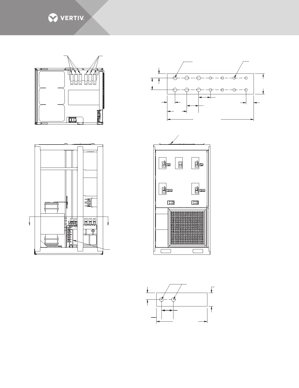
Figure 28 Electrical field connections, 800A Liebert STS2/PDU input with CB3
A A
SECTION A - A
SEE SECTION A - A
Ground busbar
(not shown) is
located under
Source #1
busbars.
Ground Busbar
See busbar detail.
Breaker
Section
CB6
CB1 CB2
CB7
CB5
CB4
CB3
FRONT
Doors and Accent Panels
Not Shown
LEFT SIDE
Accent Panels Not Shown
.46" DIA.
(11.7mm)
.75"
(19.1mm)
.56" DIA.
(14.3mm)
Typ. 6 Places
.41" DIA.
(10.3mm)
Typ. 8 Places
2"
(50.8mm)
1" (25.4mm)
1. Phase, neutral and ground busbars are 1/4" thick.
2. Control wiring and power wiring must be run
in separate conduit. Output cables should be run
in a separate conduit from input cables.
3. Aluminum and copper clad aluminum cables
are not recommended.
4. All wiring is to be in accordance with national
and local electrical codes
INPUT BUSBAR DETAIL, TYPICAL
GROUND BUSBAR DETAIL
PSP11014
Rev. 1
1.75" (44.5mm)
1.75" (44.5mm)
1.75" (44.5mm)
Typical
0.63"
(15.9mm)
1.13"
(28.6mm)
3"
(76.2mm)
1.13"
(28.6mm)
2.88"
(73.2mm)
12.75" (323.9mm)
7.5" (190.5mm)
Source #1
Source #2
See Input
Busbar Detail
ABC
ABC
ABC
1.75" (44.5mm)
Typical