Vertiv™ | Liebert® STS2/PDU
™
User Manual | Rev. 6 | 10/2017 11
The Liebert STS2/PDU output power, ground and neutral busbars accommodate a wide range of wire sizes. The
Liebert STS2/PDU busbars accommodate standard two-hole lugs.
4.2 System Grounding
Equipment grounding—Grounding is primarily for equipment and personnel safety, although proper grounding
also enhances equipment performance.
All input and output power feeds must include an equipment grounding means as required by the NEC and local
codes.
An insulated equipment ground conductor is recommended to run with each input and output power feed. The
equipment ground conductors should be at least the minimum size conductor per the NEC based on the
upstream overcurrent protection device.
4.3 Control Wiring Connections
No control wiring is needed on the standard Liebert STS2/PDU. Certain options and remote monitoring
configurations require external control wiring. See 6.0 - Options for details.
The customer must supply control wiring to the Liebert STS2/PDU for connection to any monitoring or
communication options. Top and bottom removable conduit plates are provided for control wiring conduit.
Control cables can be installed through the top or bottom of the unit through removable control conduit plates.
A top hat is provided on the 400-600A units for connecting the top entry control wiring conduits (see
Figures 13 through 21). The top hat is turned upside down and ships inside the unit. It must be removed from the
unit and flipped 180 degrees before being reinstalled (see Figure 49). The control wiring top hat does NOT
contain any knockouts for conduit. The installer must drill the appropriate-sized holes for the conduit before
attaching to the top of the Liebert STS2/PDU.
See Figures 47 and 48 for arrangement of optional cards.
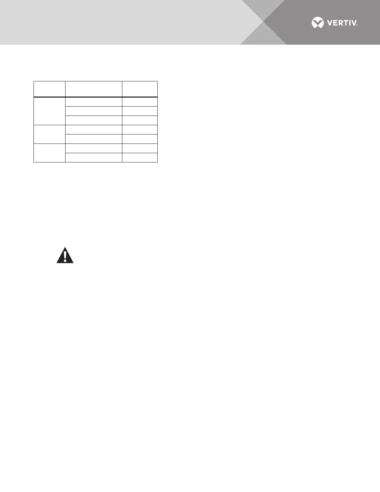
Table 3 Input/output conduit plate specifications
Rating
Maximum Number
of Conduits Size, in.
250A
12 2"
82-1/2"
63" or 3-1/2"
400-600A
6 2"
4 2-1/2" or 3"
800A
62-1/2"
53" or 3-1/2"
WARNING
Risk of electric shock. Can cause injury or death.
If conduit is used as a grounding means, adequate electrical continuity must be maintained at all conduit
connections. Using isolating bushings with a metal conduit can be a safety hazard.