Vertiv™ | Liebert® STS2/PDU
™
User Manual | Rev. 6 | 10/2017 60
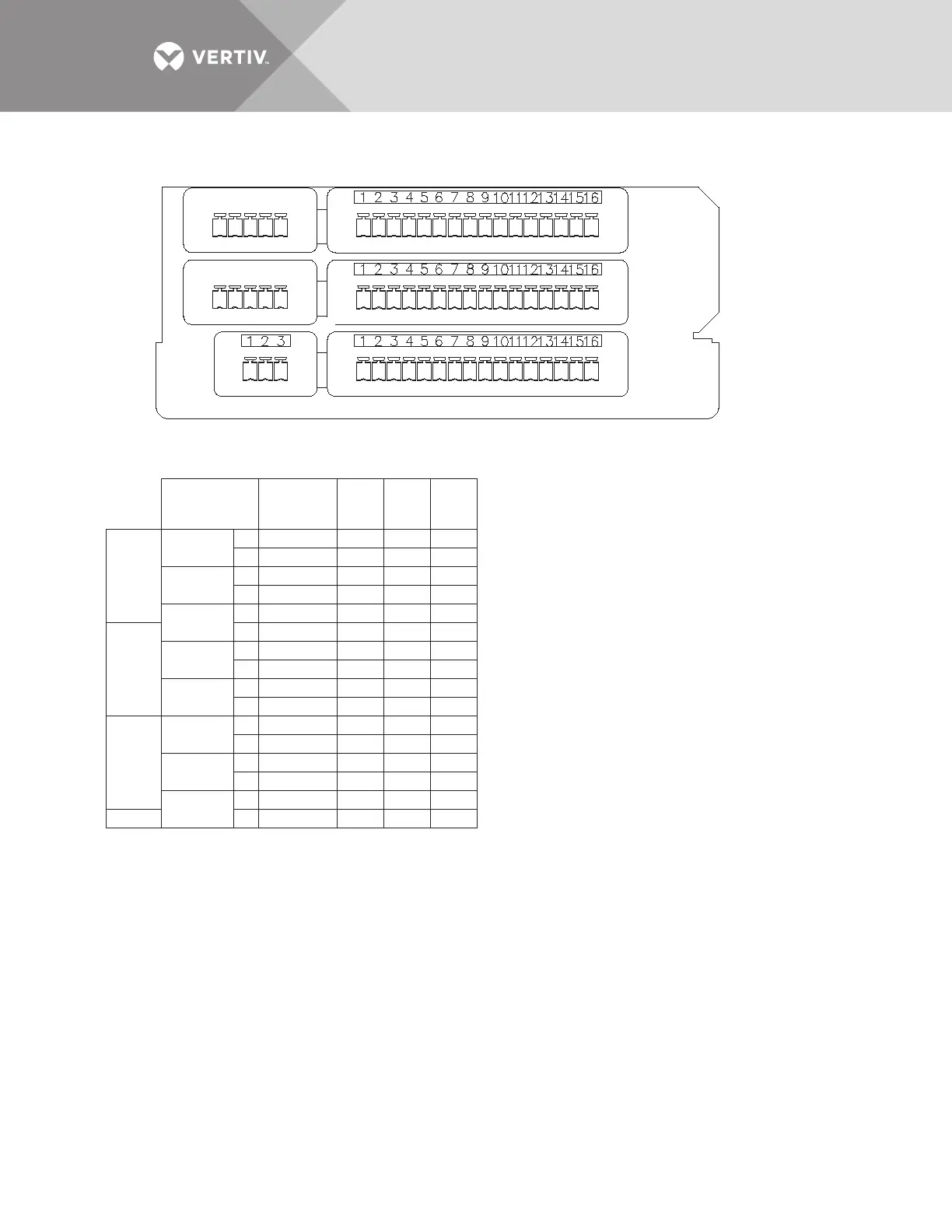
Figure 50 Control wiring for the programmable relay board option
PS213001
Rev. 2
PROGRAMMABLE RELAY BOARD
NOTES
1. Customer control wiring connection points are
Terminal Blocks 1 through 15.
2. Programmable relay board option includes eight
signal channels with two Form-C dry contacts per
channel. See table.
(C=Common, NC=Normally Closed, NO=Normally Open)
3. Refer to other portions of this document for configuring
the programmable relay board option.
4. All control wiring (by others) must be run
separate from power wiring. Control wiring runs
should not be combined in the same conduit.
5. Refer to static transfer switch control connection
diagram for location of program relay board option.
6. Contact ratings: 1amp @ 30VDC, 200mA @125VAC.
7. Maximum cable length 500 ft. (152m) with
#16AWG flexible stranded cable.
8. All wiring must be in accordance with national
and local electrical codes.
NOTE: Pin 16 not used on J71, J72 and J73
J71
J72
J73
J74
13
13 - 15
A
13 - 15
10 - 12
7 - 9
4 - 6
1 - 3
13 - 15
10 - 12
7 - 9
4 - 6
1 - 3
1 - 3
A
J73
CH8
CH7
J74
A
B
B
CH6
CH5
CH4
CH3
J72
A
A
B
B
A
B
B
7
13
1
10
10
1
4
13
4
7
1
10 - 12
4 - 6
7 - 9
1 - 3
PIN NO.CHANNEL
CH2
CH1
J71
A
A
B
B
1
7
10
4
C
14
8
2
11
14
11
14
2
5
2
5
8
2
5
8
11
NC
15
9
15
3
12
12
3
6
15
6
9
3
3
9
12
6
NO