NOTES:
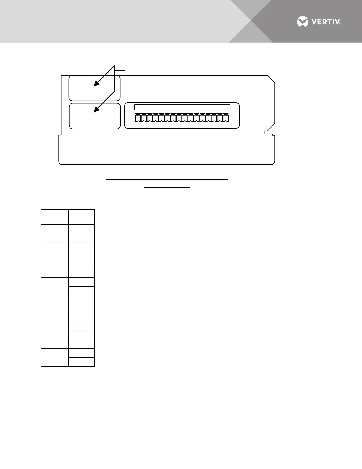
1. Customer control wiring connection points are Terminals 1 through 16
(see Table J51).
2. Customer-provided, normally open, dry contacts for user alarm messages.
3. Refer to installation, operation AND maintenance manual for configuring the input contact
isolator board option.
4. All control wiring (by others) must be run separate from power wiring. Control wiring runs
should not be combined in the same conduit.
5. Refer to static transfer switch control connection diagram for location of input contact isolator
board option.
6. Signal voltage: 100mA @ 12VDC.
7. Maximum cable length 500 ft. (152 meters) with #16 AWG flexible, stranded cable.
8. All wiring must be in accordance with national and local electrical codes.
Table J51
Input
Contact Pin No.
1
1
2
2
3
4
3
5
6
4
7
8
5
9
10
6
11
12
7
13
14
8
15
16