Vertiv™ | Liebert® STS2/PDU
™
User Manual | Rev. 6 | 10/2017 14
6.0 OPTIONS
This section discusses the options available for the Liebert STS2/PDU. The communications options are also
discussed in 12.0 - Communication Interfaces.
6.1 Programmable Relay Board
The programmable relay board (PRB) provides a means to trigger an external device when an event occurs in
the Liebert STS2/PDU. Each PRB has 8 channels. Each channel has two sets of Form-C dry contacts, rated 1A @
30VDC or 250mA @ 125VAC.
Any alarm or event may be programmed to any channel or channels. Up to ten (10) events may be programmed
to a relay. If multiple events are grouped to one relay, group the events logically to simplify troubleshooting when
an event is triggered. The same alarm or event may be programmed to more than one channel. Up to two
programmable relay boards can be installed in the Liebert STS2/PDU for a total of 16 channels. Programming is
performed through the touchscreen.
See Configuring the Programmable Relay Board Settings on page 109 for default settings and instructions
for reconfiguring the relays. See Figures 47 and 48 for the location of the PRB. See Figure 50 for wiring details.
Table 7 provides the PRB pin-out.
WARNING
Risk of electric shock. Can cause injury or death.
All options must be installed by Vertiv Services or Vertiv factory-authorized service provided by a Vertiv
distributor. The option area and customer control cable area contain hazardous voltages if any of the
input sources are on, even when the unit is in bypass. Turn Off all power sources before installing
customer control cables to any option.
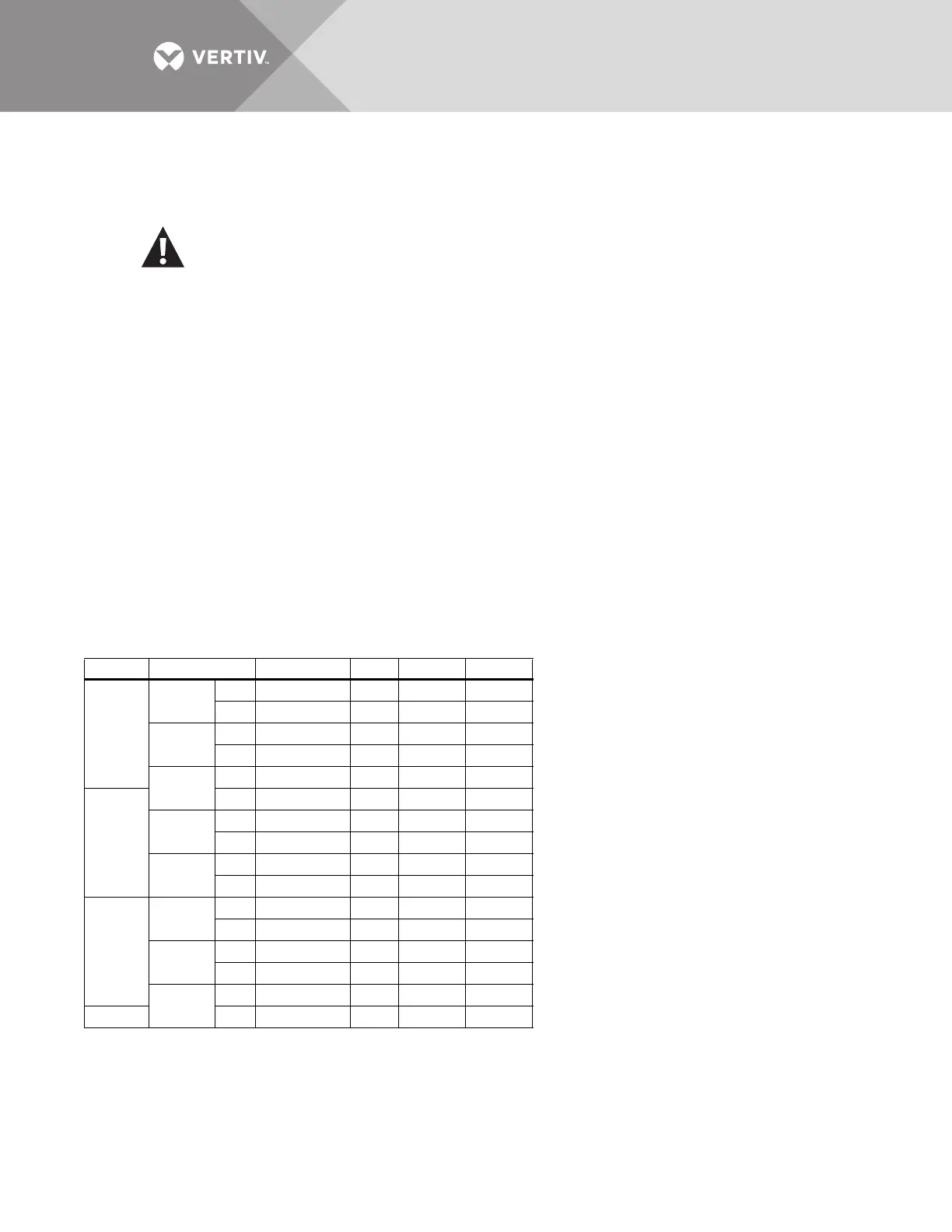
Table 7 Programmable relay board pinout
Channel Pin No. C N.C. N.O.
TB1
CH1
A1-3 12 3
B4-6 45 6
CH2
A7-9 78 9
B 10-12 10 11 12
CH3
A 13-15 13 14 15
TB2
B1-3 12 3
CH4
A4-6 45 6
B7-9 78 9
CH5
A 10-12 10 11 12
B 13-15 13 14 15
TB3
CH6
A1-3 12 3
B4-6 45 6
CH7
A7-9 78 9
B 10-12 10 11 12
CH8
A 13-15 13 14 15
TB4
B1-3 12 3
Key: N.O. = Normally Open; N/C. = Normally Closed; C = Common
Note: Pin 16 not used on TB1, TB2 and TB3.