PSP13200
Rev. 1
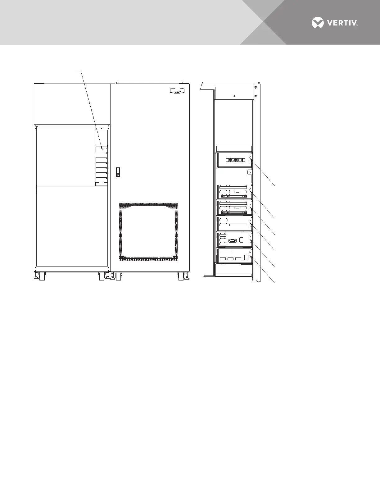
NOTES
1. Typical options are shown.
2. Maximum of two programmable
relay boards can be used.
CONTROL WIRING
FRONT
Front Door Not Shown
Comms Board for
Liebert SiteScan,
External and Internal
Modem Interface (Option)
Input Contact Isolator Board
(Option) or Programmable Relay
Board (Option) See Note 2
See Option
Location Detail
OPTION LOCATION DETAIL
Network Interface
Card (NIC) (Option)
Remote Source
Select (Option)
Programmable Relay
Board (Option) See Note 2
Programmable Relay
Board (Option) See Note 2