Vertiv™ | Liebert® STS2/PDU
™
User Manual | Rev. 6 | 10/2017 10
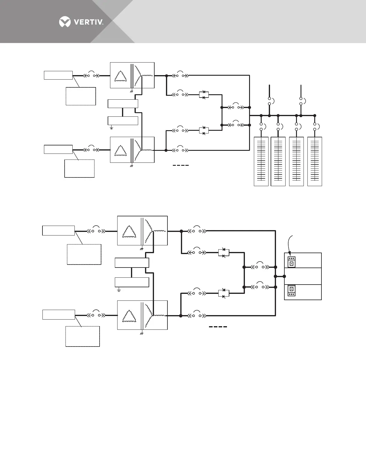
Figure 5 Typical Liebert STS2/PDU, one-line diagram, with inline distribution, dual static switch output circuit breakers
Figure 6 Typical Liebert STS2/PDU, one-line diagram, with I-Line distribution, dual static switch output circuit breakers
The input and output power wire size should be based on the overcurrent protection device, observing the NEC
and local codes.
Source 1
Source 2
Surge
Suppression
Optional
Surge
Suppression
Optional
Transformer 1
Transformer 2
Ground
CB6
CB4
Subfeed 1
Optional
Subfeed 2
Optional
CB1
CB2
CB5
CB7
SS1
SS2
Field-Supplied Wiring
42-Pole Distribution
Panelboard, Typical
PSP12003
Rev. 3
CB3
CB12
CB13
CB3A
Neutral
CB8 CB9 CB10 CB11
Source 1
Source 2
Surge
Suppression
Optional
Surge
Suppression
Optional
Transformer 1
Transformer 2
Ground
CB6
CB4
CB1
Output
Breaker(s)
I-Line Panelboard
CB2
CB5
CB7
SS1
SS2
Field-Supplied Wiring
PSP12001
Rev. 2
CB3
CB3A
Neutral