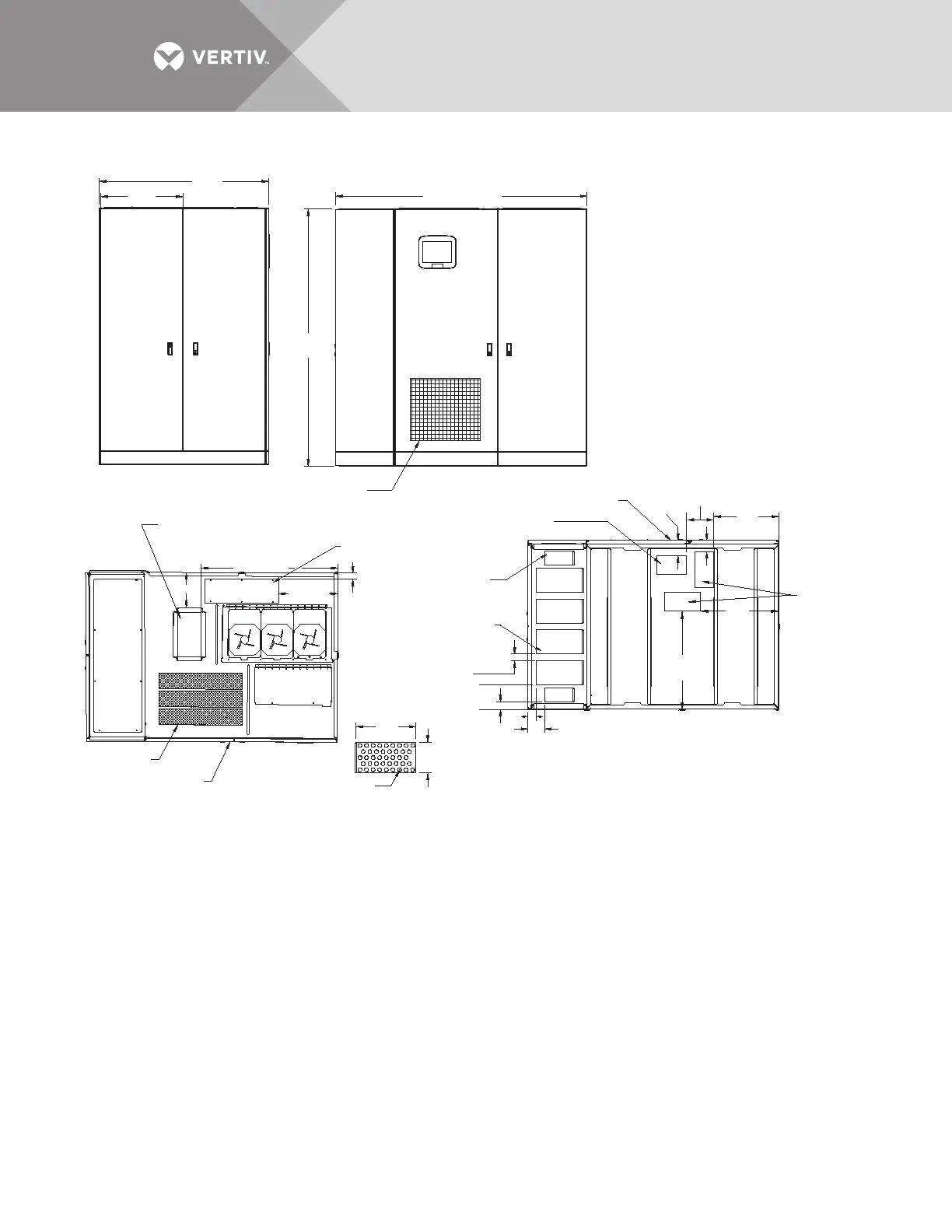
BOTTOM
TOP
3.3"
(84mm)
4.4"
(112mm)
FRONT
7.2"
(182.9mm)
7"
(178mm)
13.6"
(345mm)
2.3
39.6"
(1006mm)
11.5"
DETAIL A
.88" DIA.
Typ. 42 Places
1.9" (48mm)
Typical
2.3" (58mm)
4.9"
(124mm)
1.8'
(46mm)
8"
(203mm)
28.3"
(719mm)
22.7"
(577mm)
18.9"
(480mm)
Air Exhaust
Bottom Input
Power Conduit
Entry Area,
2 Places
10.4" x 5.4"
(264 x 137mm)
1. Approximate weight: 400A - 4608 lb. (2095kg)
600A - 5692 lb. (2587kg).
2. 18" (457mm) clearance above unit required for
air exhaust.
3. Installation and service access required in
front and left side only.
4. Keep cabinet within 15 degrees of vertical.
5. Color - IBM off-white.
6. Approximate heat output:
400A - 19,295 BTU/hr (5.66 kW)
600A - 29,238 BTU/hr (8.57 kW).
7. Unit bottom is structurally adequate for
forklift handling.
8. Open doors to replace air filter. Disposable
type size 1 x 25 x 25 (25 x 635 x 635mm).
9. Top and bottom cable entry available through
removable access plates. Remove, punch to suit
conduit size and replace.
PSP11402
Rev. 2
Bottom Control Conduit
Entry Area, 8.7" x 5.5"
(221 x 140mm)
Air Intake Area
Do not block air filter.
Bottom Subfeed
Conduit Entry Area
8.3" x 4" (211 x 102mm)
120° Front Door Swing
All doors with lift-off hinges
Top Control
Conduit Box
12.9" x 6.8"
(325 x 130mm)
See Drawing
PSP13401
Top Input Power
Conduit Entry Area
21.4" x 7"
(544 x 178mm)
17.2"
(437mm)
LEFT SIDE
FRONT
49.4"
(1255mm)23.9"
(606mm)
73.3" (1861mm)
77.4"
(1966mm)
Bottom Output
Conduit Entry
Area, 4 Places
See Detail A