Vertiv™ | Liebert® STS2/PDU
™
User Manual | Rev. 6 | 10/2017 48
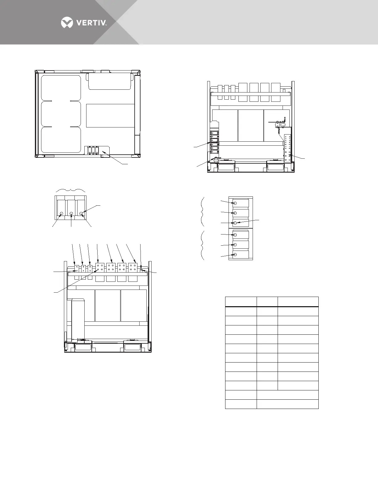
Figure 38 Electrical field connections, 800A Liebert STS2/PDU interconnect wiring, breaker section
PSP11019
Rev. 0
SECTION A - A
Breaker Section
SECTION B - B
BREAKER SECTION
SECTION C - C
STS SECTION
TB1
See Enlarged
Detail Below
TB1-1 TB1-2 TB1-3
TB2 and TB3
See Enlarged
Detail Below
TB2-1
TB2-2
TB2-3
TB3-1
TB3-2
TB3-3
H1 H2 H3 X1 X2 X3 X0 Shield Wire
0.50" DIA.
(12.7mm)
Typical,
3 Places
0.50" DIA.
(12.7mm)
Typical,
6 Places
.42 DIA.
(10.7mm)
Typical,
6 Places
.56 DIA.
(14.2mm)
Typical,
16 Places
.38 DIA.
(9.6mm)
Ground Busbar
See Ground
Busbar Details in
Drawing PSP11018
TB2
TB3
TB1
Neutral Busbar
See Drawing
PSP11018
T2
T1
NOTES
1. Interconnection wiring from T1 to TB1, 2, 3 and neutral busbars are
attached to T1 and shipped in the STS section.
2. Refer to drawing PSP11018 for section location details and for
neutral and ground busbar details.
Table 8 Interconnection wiring, from STS
section to breaker section
From T1 To Wire Number
H1 TB1-1 7AA and 7BB
H2 TB1-2 8AA and 8BB
H3 TB1-3 9AA and 9BB
X1 TB2-1 13AA and 13BB
X1 TB2-2 13CC and 13DD
X2 TB2-3 14AA and 14BB
X2 TB3-1 14CC and 14DD
X3 TB3-2 15AA and 15BB
X3 TB3-3 15CC and 15DD
X0 Neutral Busbar
Shield Wire Ground Busbar