Vertiv™ | Liebert® STS2/PDU
™
User Manual | Rev. 6 | 10/2017 79
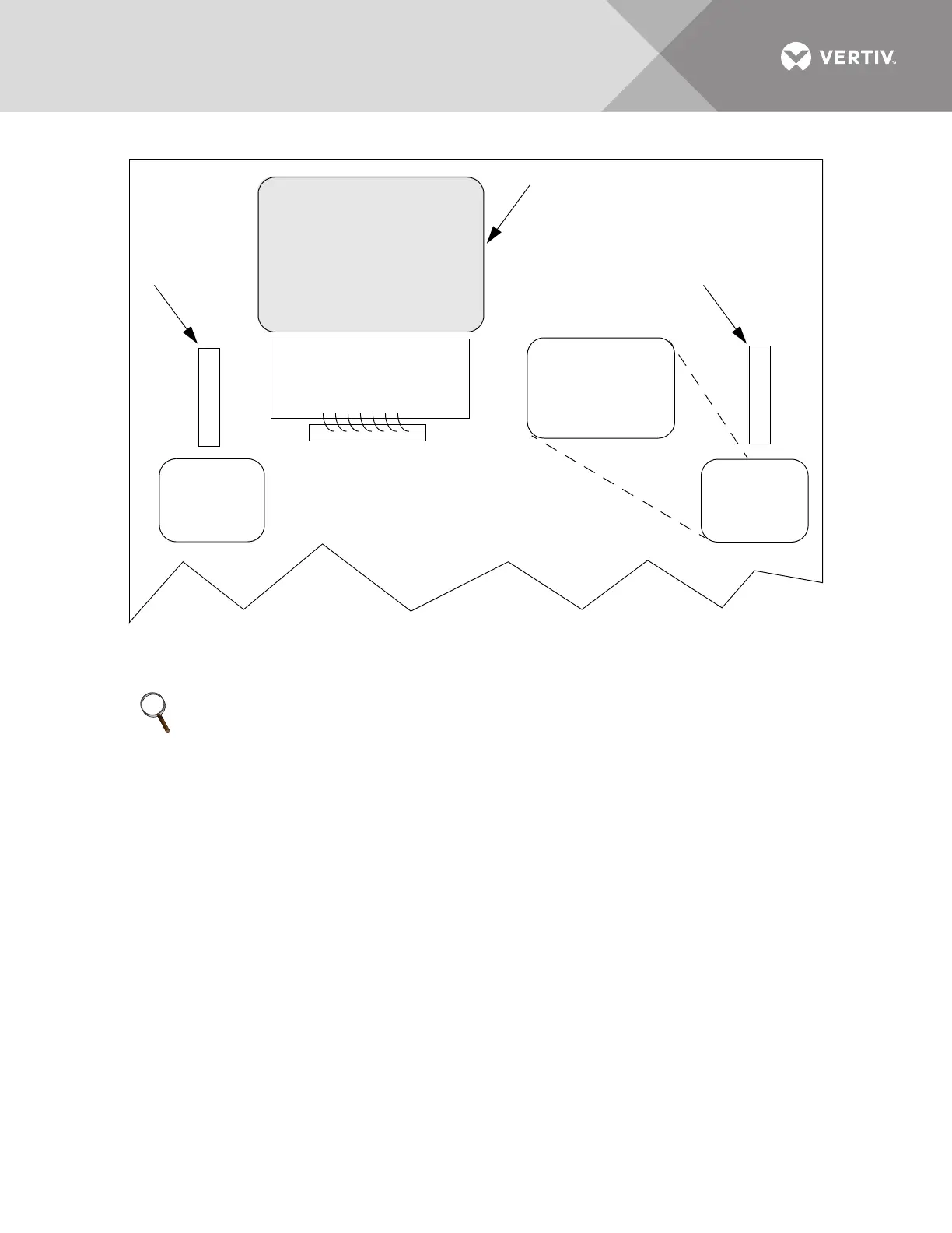
Figure 60 Gate board viewing slot locations
10.4.1 Bypass Procedures for Source 1
To bypass the switch for Source 1:
1. Verify Source 1 is supplying power via the Mimic.
• If the Color Graphical Display is not available, check the gate driver board LEDs through the slots in the control panel.
See Figure 60.
2. Remove interlock key from CB5 and place it in the CB4 interlock.
3. Open the alternate source input breaker CB2.
4. Rotate and remove the CB2 interlock key.
5. Insert the key in the CB4 bypass breaker interlock.
6. Rotate interlock keys in CB4 bypass breaker interlock to retract interlock.
7. Close bypass breaker CB4.
8. Verify the breaker status on the Mimic screen.
9. Open source input breaker CB1.
10. Rotate the CB1 interlock key and remove it to lockout the breaker.
11. Secure the key, per your site’s lockout/tagout procedure.
12. Open output breakers CB3 and CB3A (if supplied) to remove power and isolate the static switch from the load.
NOTE
If you wish to bypass the Source 1 static transfer switch but Source 2 is presently active, you must first
transfer to Source 1. See 10.2 - Manual Transfer / Preferred Source Selection.
Green LEDS on the
Gate Driver Board are
viewable through this
slot indicate that the
STS is on Source 1
GREEN LEDS ON THE
GATE DRIVER BOARD
ARE VIEWABLE
THROUGH THIS SLOT
INDICATE THAT THE
STS IS ON SOURCE 1
Viewing Slot
for the Source 1
Gate Drive Board
Touchscreen
GREEN LEDS ON THE
GATE DRIVER BOARD
ARE VIEWABLE
THROUGH THIS SLOT
INDICATE THAT THE
STS IS ON SOURCE 2
Viewing Slot
for the Source 2
Gate Drive Board