Vertiv™ | Liebert® STS2/PDU
™
User Manual | Rev. 6 | 10/2017 33
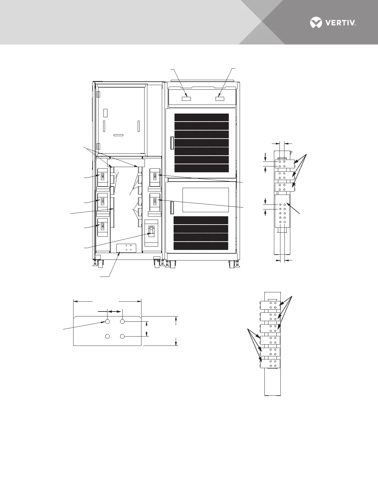
Figure 23 Electrical field connections, 250A Liebert STS2/PDU input/output with CB8
FRONT
Doors and Accent Panels
Not Shown
CB5
A
B
C
A
B
C
A
B
C
.51" DIA.
(13mm)
Typ. 4 Places
Neutral
Output
Busbar
See Ground
Busbar Detail B
CB8
CB3
See Source,
Neutral, and
Output Busbar
Detail A
CB4
CB1
Output
Source 1
Source 2
CB6
CB7
CB2
1. Phase, neutral and ground busbars are 1/4" thick.
2. Control wiring and power wiring must be run in separate conduit.
Output cables should be run in a separate conduit from input cables.
3. Aluminum and copper clad aluminum cables are not recommended.
4. All wiring is to be in accordance with national and local electrical codes
Source 1 Busbar
Approx. 7.5 X 3.2
(191 x 81mm)
1/2"-13 PEM Nut
Typ. 4 Places
Output Busbar
Approx. 7.5" x 3.2"
(191 x 81mm)
1/2"-13 PEM Nut
Typ., 4 Places
Neutral Output
Busbar
12.6 X 5.75
(320 x 146mm)
1/2"-13 PEM Nut
Typ. 10 Places
Source 2 Busbar
Approx. 7.5 X 3.2
(191 x 81mm)
1/2"-13 PEM Nut
Typ. 4 Places
SOURCE, NEUTRAL,
& OUTPUT
BUSBAR DETAIL A
GROUND BUSBAR
DETAIL B
PSP11009
Rev. 0
1.75"
(44mm)
Typical
1.75" (44mm)
1.77"
(45mm)
8" (203mm)
3.5"
(89mm)
1.75"
(44mm)
Typical
1.75"
(44mm)
Typical