Vertiv™ | Liebert® STS2/PDU
™
User Manual | Rev. 6 | 10/2017 53
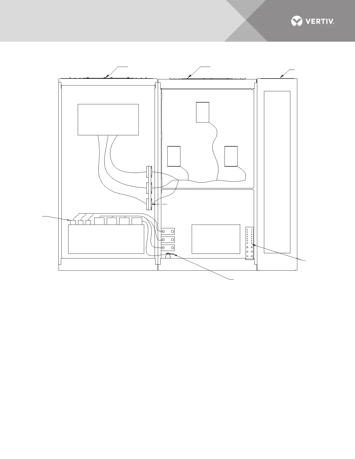
Figure 43 Electrical field connections, 800A Liebert STS2/PDU interconnect wiring, right side one-line
PS
Rev. 0P11026
NOTES
1. Interconnection wiring from T1 to TB1, 2, 3 and neutral busbars are attached to T1 and shipped in the STSsection.
See drawing PSP11019 for details.
2. Interconnection wiring from CB1, CB2 and CB3 to STS section are attached to CB1, CB2 and CB3 and shipped
in the breaker section. See drawing PSP11020 for details.
FRONT
Accent Panels Not Shown
CB2
Breaker
Section
CB1
STS
Area
TB3
TB2
TB1
Neutral
Busbar
CT
See
Drawing
PSP11019
For Details
STS
Section
H1 H2 H3
X3 X0X1 X2
Transformer
T1
Transformer
T2
W21
W22
W23
W24
W25
W26
Ground
Busbar
Distribution
Section
W27
W28
W29
CB3
See Drawing PSP11020
Section D - D
See Drawing PSP11020
Section E - E