Maintenance2722−2/A1
Winterthur Gas & Diesel Ltd.
6/ 7
5.2 Installation
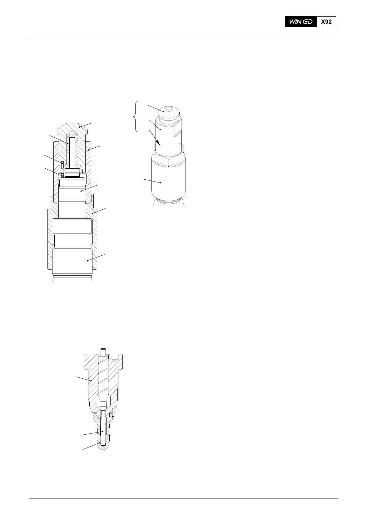
7) Make sure that the nozzle needle (2,
Fig. 5), is removed from the nozzle
body (3).
8) Attach the nozzle body (3, Fig. 5) with
coupling nut (4) to the injection valve
(5) on the injection test bench.
9) Make sure the dowel pin (2) is installed.
10) Screw the guide bush (A2) of tool
94278B onto the nozzle body (3).
11) Put the nozzle tip (1) into mounting
cylinder (A1) of tool 94278B and align
the recess in the nozzle tip with the
dowel pin (A3).
12) Guide the mounting cylinder (A1) with
the inserted nozzle tip (1) into the guide
bush (A2).
13) Turn the mounting cylinder (A1) until
the recess of the nozzle tip aligns with
the dowel pin (2).
14) The mounting cylinder lowers a little bit
and can not be turned anymore.
15) Use copper or rubber hammer to tap
the mounting cylinder (A1) fully down.
16) Screw the guide bush (A2) out to
remove the nozzle assembly tool
94278B.
17) Remove coupling nut (4) and nozzle
body (3).
18) Use clean diesel oil, or clean kerosene
to clean the nozzle needle (2, Fig. 6).
19) Use a clean, low-pressure air supply to
dry the needle (2).
20) Put the needle into the nozzle body (3)
and nozzle tip (1). Make sure that the
the needle moves freely.
21) Assemble the injection valve, see
paragraph 6.
2015
Injection Valve: Disassemble, Checks, Assemble Injection Valve with FAST
Fig. 5
1
A1
4
94278B
A2
A2
A1
A3
A3
2
WCH02742
WCH02742
3
4
5
1
3
WCH02401
Fig. 6
2