Maintenance
2751−2/A1
Winterthur Gas & Diesel Ltd.
3/ 7
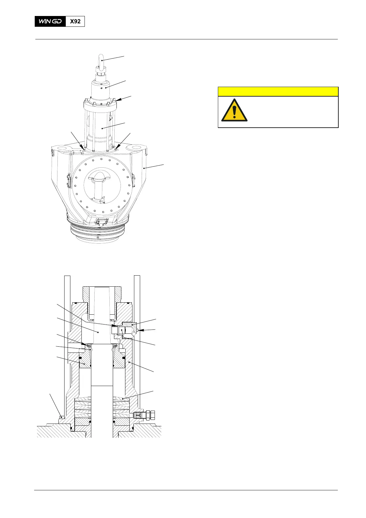
2. Exhaust valve −
disassemble
CAUTION
During this procedure, do
the work in a clean area.
Electrical welding is not
permitted.
2.1 Valve drive − disassemble
1) Attach the crane hook to the eye bolt
(19, Fig. 2).
2) Remove the six nuts (21).
3) Remove the top housing (3, 170kg).
4) Disconnect the electrical connection
from the valve stroke sensor (28).
5) Remove the two screws (29).
6) Remove the transmitter housing (27).
7) Remove the valve stroke sensor (28).
8) Remove the O-ring (41).
9) Remove the cap screw (42).
10) Remove the bottom housing (2, 100kg)
with two M12 eye bolts and a rope.
2.2 Valve spindle − remove
1) Remove the circlip (33).
2) Push the piston (16) down, then
remove the valve cotters (15).
3) Remove the piston (16) from the valve
spindle (7).
4) Remove the cup springs (18).
5) Use two M24 eye bolts and two ropes
to to lift the valve cage (1700 kg). Make
sure that the valve spindle (7) does not
move.
6) Lower the valve cage (1) on to its side.
2015
Exhaust Valve: Disassemble and Assemble
3
2
1
42
21
19
29
27
28
41
7
WCH02355
2
18
Fig. 2
33
16
15
42
42
WCH02975