Maintenance
3326−2/A1
Winterthur Gas & Diesel Ltd.
1/ 13
Crosshead Pin − Removal / Installation / Clearance
Checks
Tools:
1 Spur-geared trolley 94015-008 1 Platform 94143
2 Manual ratchet (H1) (H6) 94016−015 1 Platform 94144
2 Chain block (H2) (H7) 94017-004 1 Edge protector 94319
2 Chain block (H3) (H8) 94017-040 1 Support 94322
1 Chain block (H4) 94017-047 1 Bracket 94322B
2 Chain block (H5) (H9) 94017-051 1 Lifting tool 94324
2 Shackles 94019L 1 Chain 94325
1 Shackle 94019N 2 Lifting tools 94337
2 Shackle 94019P 1 Deviation pipe 94117C
1 Sling 94039-057 1 Deviation pipe 94117B
2 Eye bolts 94045-M20 6 Eye bolts M56
1. Preparation 1.......................................................
2. Crosshead Pin − Removal 2.........................................
3. Guide Shoes − Removal 9...........................................
4. Guide Shoes − Installation 10.........................................
5. Crosshead Pin − Installation 10.......................................
6. Clearance Checks 13................................................
7. Completion 13.......................................................
1. Preparation
WARNING
Injury Hazard: Before you
operate the turning gear,
make sure that no
personnel are near the
flywheel or in the engine.
1) Read the data in 0012−1 General
Guidelines for Lifting Tools.
2) Operate the turning gear to move the
crank of the related cylinder to BDC.
3) Keep the turning gear engaged to
prevent an accidental engine start.
4) Install the platforms (94143, 94144),
refer to 3301−1.
5) Remove the round nuts from the elastic
studs on the connecting rod, see
9403−4.
6) Remove the top end bearing cover,
refer to 3303−5.
7) Disconnect the connection from the
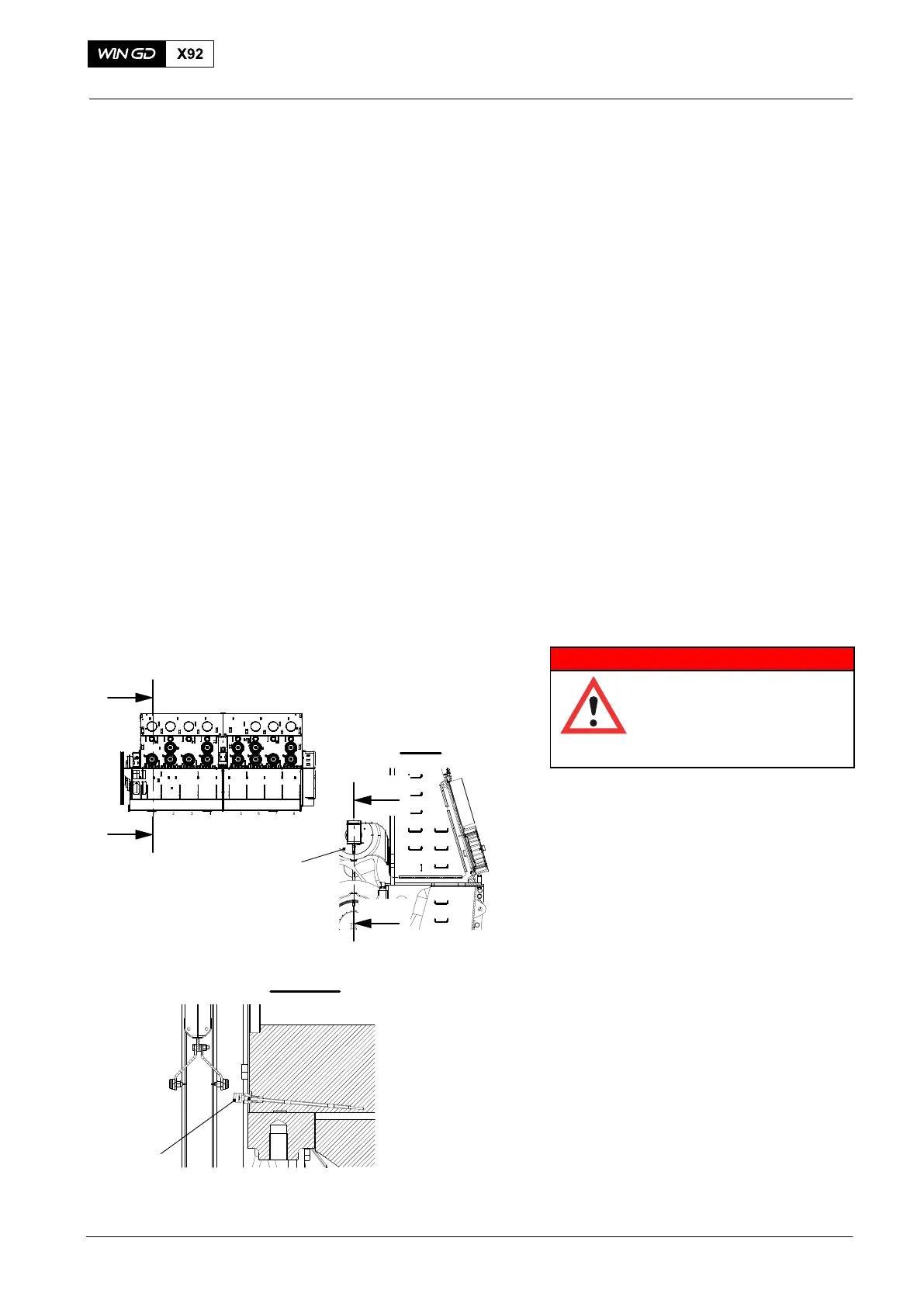
temperature sensor (2, Fig. 1)
8) Remove the temperature sensor (2)
from the crosshead (1).
9) Put protection on the oil inlets of the
crosshead pin to prevent damage and
contamination.
2016−10
6−10
Crosshead
I
I
I - I
III
III
III - III
2
Fig. 1
1
WCH3739