Maintenance
3326−2/A1
Winterthur Gas & Diesel Ltd.
13/ 13
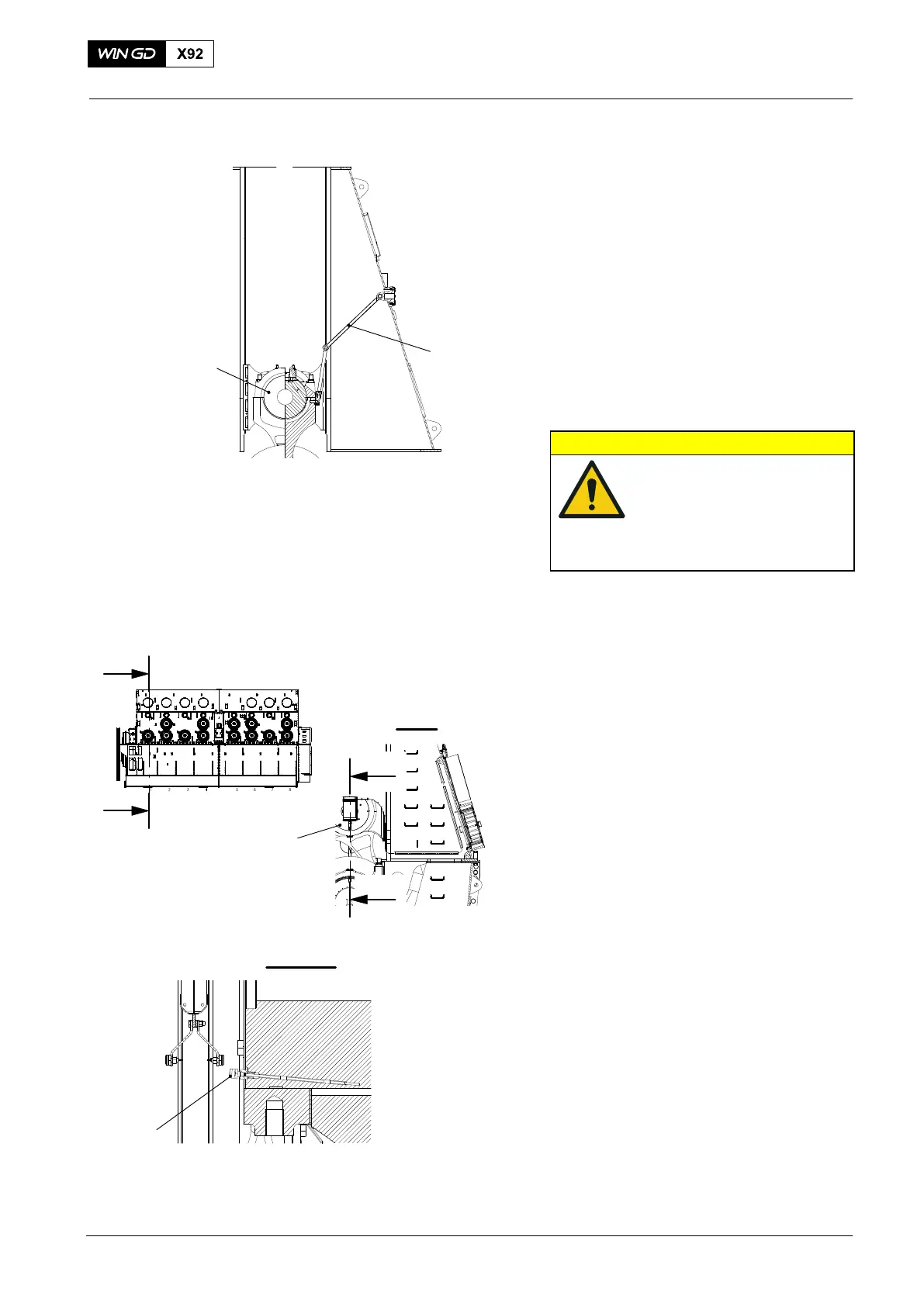
Note: During step 37), make sure that the
elastic bolts in the connecting rod
align with the holes in the
crosshead pin.
37) Carefully lower the crosshead pin (2,
Fig. 29) on to the connecting rod.
38) Use an applicable tool and sufficient
personnel to remove the two lifting
tools (94337) from the connecting rod.
39) Remove all manual ratchets, eye bolts
and chain blocks.
40) Remove the protection from the
crosshead pin (2).
CAUTION
Damage Hazard: Damage
will occur to an incorrectly
connected toggle lever.
Make sure that you
connect the toggle lever
correctly.
41) Connect the toggle lever (1) to the
crosshead pin (2). make sure that the
toggle lever is in the position shown.
6. Clearance Checks
1) Do the clearance checks, refer to
0330−1 Crosshead pin.
7. Completion
1) Apply Loctite 243 to the thread of the
temperature sensor (2, Fig. 30).
2) Attach the temperature sensor (2) to
the crosshead (1).
3) Connect the electrical connection to the
temperature sensor (2).
4) Install the round nuts to the elastic
studs on the connecting rod, refer to
9403−4.
5) Install the top bearing cover, refer to
3303−5.
6) Disengage the turning gear.
7) Set to on the lubricating oil pump.
8) Make sure that the crosshead and the
bottom end bearings of the connecting
rod have sufficient lubrication.
9) Set to off the lubricating oil pump.
2016−10
Crosshead Pin − Removal / Installation / Clearance Checks
1
2
WCH02438
Note: The crank
is at BDC.
Fig. 29
I
I
I - I
III
III
III - III
2
1
WCH3739
Fig. 30