Maintenance
3403−1/A1
Winterthur Gas & Diesel Ltd.
1/ 6
Removal and Installation
Tools:
1 Lifting tool 94209 1 Insertion funnel 94342
2 Distance holders 94230 1 Cover plate 94345
1 Piston suspension device 94341 1 Device 94350
2 Distance plates 94341A/B
1. Preparation
WARNING
Injury Hazard: Before you
operate the turning gear,
make sure that no
personnel are near the
flywheel, or inside the
engine.
1) Stop the engine, see the procedure in
Operation Manual 4002−2.
2) Let the engine temperature decrease
before you start the removal procedure.
3) Make sure that all tools and equipment
are clean.
4) Remove the cylinder cover, refer to
2708−1.
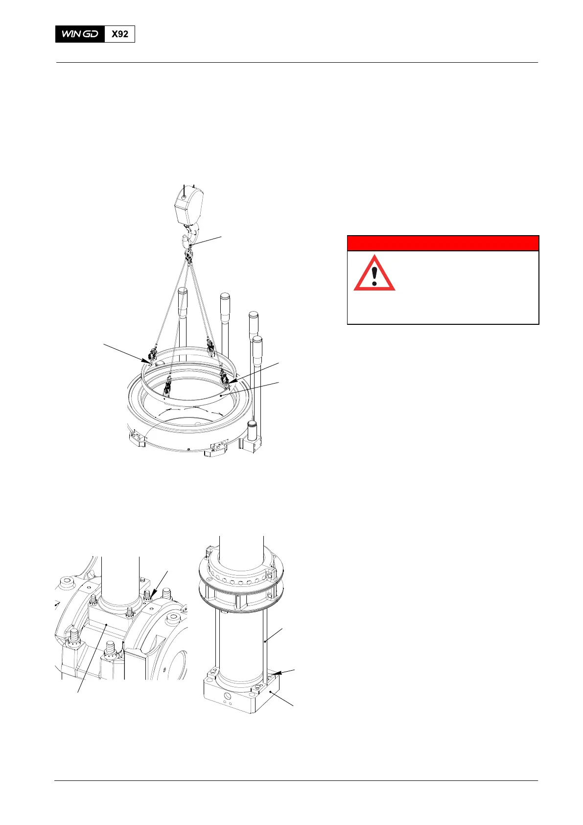
5) Attach the four plates (1, Fig. 1) to the
antipolishing ring (2) with the four
screws M12x25 (3).
6) Connect the crane hook to the lifting
tool (94209).
7) Attach the lifting tool (94209) to the the
antipolishing ring (2).
8) Look at the area where the piston
stroke ends. If there is a wear edge,
see the procedure in 2124−3.
9) Use the turning gear to turn the crank
to BDC.
10) Remove the four round nuts (1, Fig. 2)
from the piston rod foot (2), refer to
9403−4.
11) Attach the two distance holders
(94230) to the piston rod foot (2) with
the four screws M24x60 (3).
2015
Piston
94209
Fig. 1
1
2
WCH02943
3
1
2
Fig. 2
94230
2
3
WCH02943