Maintenance3403−1/A1
Winterthur Gas & Diesel Ltd.
2/ 6
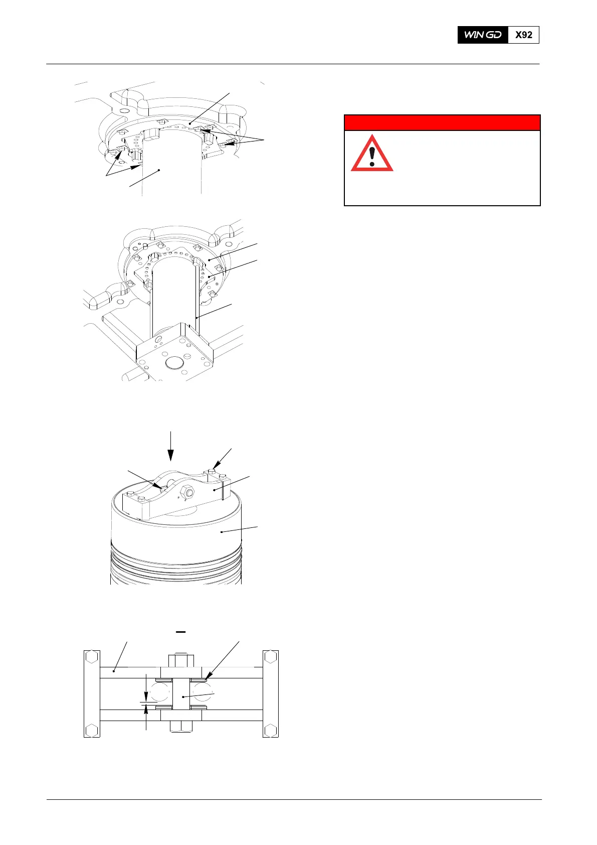
12) Remove the four inner bolts (2, Fig. 3)
from the support (1).
WARNING
Injury Hazard: Before you
operate the turning gear,
make sure that no
personnel are near the
flywheel, or inside the
engine.
13) Use the turning gear to turn the crank
to TDC until the two distance holders
(94230) are near to the piston rod
gland (2,Fig. 4). The piston rod
gland (2) is pushed out of the
support (1).
14) Make sure that the two distance
holders (94230) stay in line with the
gland box.
15) Clean the threads of the piston
suspension device (94341, Fig.5) with
water.
16) Put oil on the threads and the surfaces
of the four screws (1).
17) Attach the piston suspension device
(94341) to the piston (2) with four
screws (1).
18) Torque the screws (1) to 60 Nm.
Note: Before you use the suspension
device (94341) for the first time,
the axial clearance between the
crane hook and suspension device
must be adjusted.
Note: The axial clearance between the
plates of the suspension device is
related to the size of the crane
hook. You use the plates (94341A)
to adjust this clearance.
19) Put the applicable quantity of plates
(94341A) in position to get the axial
clearance to between 2.0 mm and
5.0 mm.
20) Connect the crane hook to the piston
suspension device (94341).
21) Make sure the clearance between the
crane hook and the distance plate
94341A is between 2.0 mm and
5.0 mm.
2015
5
Piston: Removal and Installation
94341
94341A
1
2
2
Fig. 3
Fig. 4
I
1
2
94341
94341A
I
Fig. 5
94230
3
1
2
3
WCH02943
WCH02943
WCH02943
2.0 mm to 5.0 mm