Maintenance
2722−2/A1
Winterthur Gas & Diesel Ltd.
7/ 7
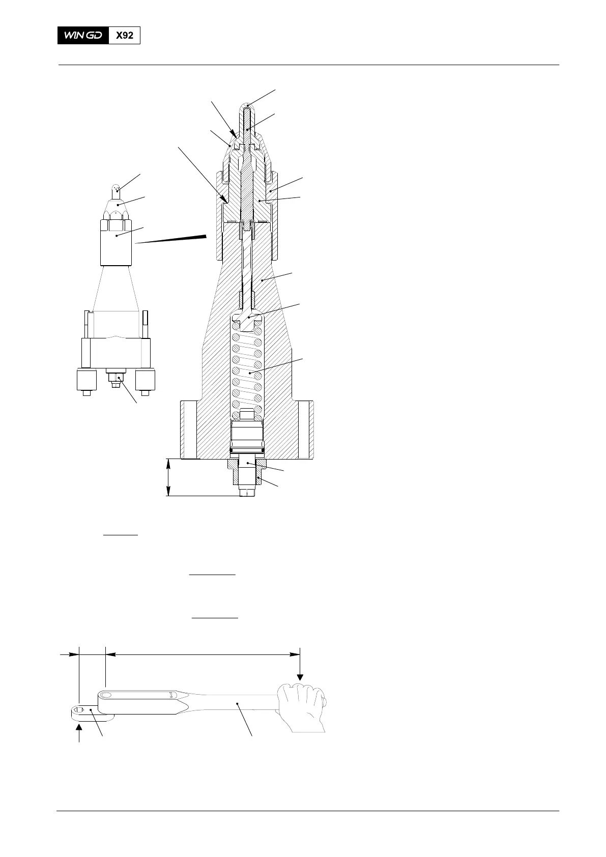
6. Assemble
6.1 Injection valve − assemble
1) Clean the contact surface of nozzle
body (2) and nozzle holder (10).
D Contact surface must be dry, clean and
free of lubricants.
2) Put the nozzle body (2) together with
the inserted nozzle needle (5) in
position on the nozzle holder (10). Two
10 mm dowel pins in the nozzle holder
give you the exact position.
3) Apply a thin layer of Never-Seez NSBT
to the thread and seating face of the
coupling nut (6).
4) Attach the coupling nut (6) over the
nozzle body (2) to the nozzle holder
(10) with your hand.
5) The coupling nut (6) must be tightened
with 200 Nm and then turned by an
additional 30 degrees. See the formula
shown in Fig. 6 for the torque
calculation with extension 94022D−70:
D TS = the applicable torque setting for the
torque spanner.
D TT = the specified torque setting for the
coupling nut and clamping nut.
D D1 = the distance from the center of the
square drive to the center of the hand
grip.
D D2 = the distance from the center of the
square drive to the center of the adapter.
6) Apply a thin layer of Never-Seez NSBT
to the thread and seating face of
clamping nut (7).
7) Use the wrench extension 94022D−55
and tighten the clamping nut (7)
according to the formula in Fig. 6 to
250 Nm.
8) Apply oil to tappet (9) and insert it
together with compression spring (8)
into the nozzle holder (10)
9) Turn in the spring tensioner (3) until it
protrudes by X = 48 mm.
D X = 48 mm corresponds to an opening
pressure of 375 bar. Adjust if necessary.
10) Lock the spring tensioner with collar nut
(11).
11) Do a check of the injection valve, see
paragraphs 3.1 and 3.2.
12) Install the injection valve, refer to
2722−1.
2015
Injection Valve: Disassemble, Checks, Assemble Injection Valve with FAST
TS = TT x D1
D2 + D1
TS for coupling nut (6): 200 x 530
75 + 530
TS for clamping nut (7): 250 x 530
65 + 530
94011A94022D−55
D2 D1
94022D−70
= 175 Nm
= 223 Nm
2
3
6
9
8
5
WCH02946
7
6
7
4
4
3
10
Fig. 7
SEATING FACE
SEATING FACE
X
11