Maintenance6545−1/A1
Winterthur Gas & Diesel Ltd.
6/ 6
3. Installation
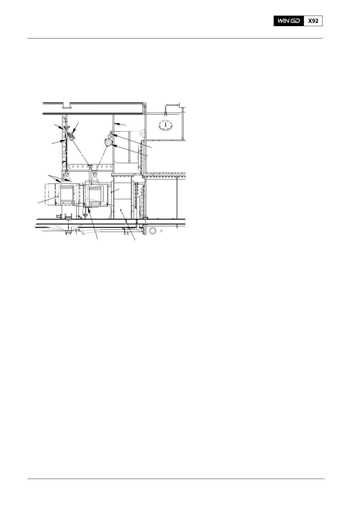
1) Put two round slings 94039-013 around
the electric motor (1, 1200kg) and
attach the slings to the hook of the
engine room crane. For the installation
of the free end motor use also lifting
tool 94651.
2) Lift and move the electric engine
according to the removal procedure to
front of the auxiliary blower casing,
refer to chapter 2.1 and 2.2.
3) Align the flange (2) with the casing (6),
see Fig. 6.
4) Use the lever chain blocks (H2) and
H1) together to move the electric motor
(1) horizontally into the casing (6).
5) Attach the flange (2) of the electric
motor (1) to the casing (6) and tighten
the screws according to manufacturers
instruction.
6) Attach the electric motor (1) to the
support (6) with four screws (3).
7) Connect the electrical connection to the
electric motor (1).
8) Remove all tools and equipment from
the work area.
4. Function check
1) Set the auxiliary blower to on, refer to the Operation Manual 4003−1/A1,
paragraph 4.6 step 1) to step 3) c).
2) Make sure that the electric motor operates in the correct direction.
Auxiliary Blower: Maintenance
2015−08
Fig. 6
94039−013
94019L
WCH03041
1
4
94017−029
94017−028
94019K
H2
H1
2
3
5
6