Maintenance
2708−1/A1
Winterthur Gas & Diesel Ltd.
1/ 6
Removal and Installation of Cylinder Cover, Water Guide
Jacket, Exhaust Valve
Tools:
1 Lifting tool 94215 1 Cylinder cover support 94266
10 Pre-tensioning jacks 94215A
1 Suspension device 94265
Hydraulic equipment see 9403−2
1. Preparation
1) Stop the engine, see the procedure in
Operation Manual 4002−2.
2) Let the engine temperature decrease
before you start the removal procedure.
3) Make sure that all tools and equipment
are clean.
4) Close the starting air supply valves and
the control air valves 930-V03 and
930-V04 manually, see the control
diagram in Operation Manual 4003−2.
WARNING
Injury Hazard: You must
put on safety goggles and
gloves when you do work
on hot components. Oil
can come out as a spray
and cause injury.
5) Close the cylinder inlet butterfly valves
to the cooling water system.
6) Open the drain valve to the cylinder
cooling water from the applicable
cylinder, see the Operating Manual in
8017-1.
7) Close the valves from the fuel supply
and make sure there is no pressure in
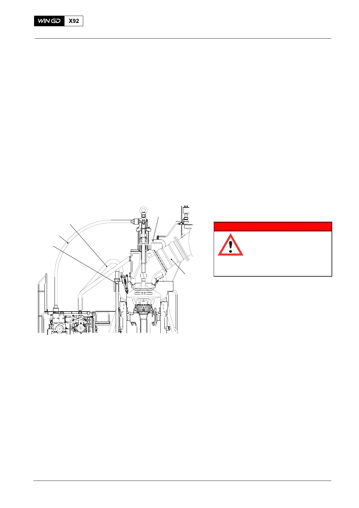
HP fuel pipe (5, Fig.1).
8) Remove the hydraulic pipe (4) for
exhaust valve drive, refer to 8460−1.
9) Remove the HP fuel pipe (5), refer to
8733−1.
10) Make sure that there is no pressure in
the cooling water pipe (1) and remove
it.
11) Remove the expansion piece (2) with
the slings, see 2751−1.
12) Close the starting air valve and
disconnect the air pipe from the
cylinder cover.
13) Disconnect all other connections to the
cylinder cover and to the exhaust valve.
2015
Cylinder Cover
3
4
5
1
2
WCH02926
Fig. 1