Maintenance3326−2/A1
Winterthur Gas & Diesel Ltd.
12/ 13
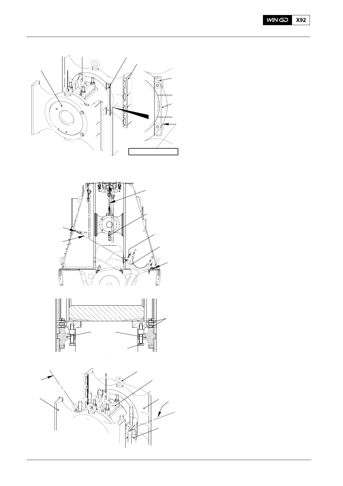
Note: The guide shoe (2, Fig. 25) can
look different.
24) Attach the two holding plates (1) to the
guide shoe (2) with the tab washers
and bolts.
25) Make sure that there is no clearance
between the holding plates (1) and
crosshead pin (3).
26) Operate the chain blocks (H5, H3 and
H8 Fig. 26) to lift the crosshead
approximately 300 mm above the
center of the pin hole (4, Fig. 7).
Note: The two supports (94322A) hold
the weight of the crosshead while
you move the connecting rod.
27) Use an applicable tool and sufficient
personnel to attach the two supports
(94322A, Fig. 26) to the guide way.
28) Torque the four bolts (1, Fig. 27) to
150 Nm.
29) Tighten the two special screws (2).
30) Attach the two manual ratchets (H1 and
H6, Fig. 28) to the shackles (94019L)
on the column and to the shackles on
the two lifting tools (94337) on
connecting rod (1). Apply a light tension
to the chains.
Note: During the step below, slowly
move the connecting rod to the
fuel side.
31) Gradually tighten the manual ratchet
H1. At the same time, keep tension on
the manual ratchet (H6).
32) Continue with step 31) until the
connecting rod (1) aligns with the
crosshead.
33) Remove the wooden block (2).
34) Lift the crosshead a small distance.
35) Loosen the two special screws (2,
Fig. 28).
36) Use an applicable tool and sufficient
personnel to remove the two supports
(94322A).
2016−10
Crosshead Pin − Removal / Installation / Clearance Checks
FUEL SIDE
1
2
94324
94045−M56
1
94337
2
WCH02437
WCH02437
2
1
NO CLEARANCE
Fig. 25
Fig. 28
3
Fig. 26
H1
94322A
H5
2
1
94322A
Fig. 27
1
2
94019L
94337
WCH03035
H3, H8
H1
H6