Maintenance
3326−2/A1
Winterthur Gas & Diesel Ltd.
11/ 13
WARNING
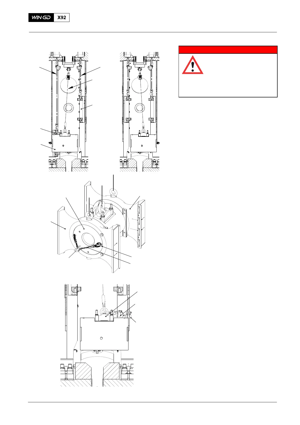
Injury Hazard: The weight
of the crosshead pin is
4830 kg. Use only
approved equipment and
sufficient personnel to lift
and move the crosshead
pin.
6) Operate the chain blocks (H4, H9) to
move the crosshead pin through the
door frame.
7) Attach the chain block (H5, Fig.21) to
the eye bolt on the lifting tool (94324).
8) Apply a light tension to the chain
block (H5).
9) Remove carefully the chain block (H4).
10) Turn the crosshead pin 90° .
Note: The guide shoe (1, Fig. 23) can
look different.
11) Remove the protection tool (94117B,
Fig.21) from the door frame.
12) Operate the chain block (H8) to lower
and align the guide shoe (1, Fig. 23)
with the crosshead pin (3).
13) Attach the two eye bolts (94045−M20)
and the chain (94325) to the crosshead
pin (3).
14) Attach the eye bolt (94045−M56,
Fig.24) to an applicable position on the
column.
15) Attach the manual ratchet (H1) to the
eye bolt (94045−M56) and the chain
(94325).
16) Operate the manual ratchet (H1) to pull
the crosshead pin (3) into the guide
shoe (1).
17) Remove the chain (94325), eye bolts
(94045−M20, 94045−M56) and manual
ratchet (H1).
18) Operate the chain block (H3) to lower
and align the guide shoe (2, Fig. 23)
with the crosshead pin (3).
19) Attach the eye bolts (94045−M20) and
the chain (94325) to the other side of
the crosshead pin.
20) Attach the eye bolt (94045−M56) to an
applicable position on the column.
21) Attach the manual ratchet (H1) to the
eye bolt (94045−M56) and the chain
(94325).
22) Operate the manual ratchet (H1) to pull
the crosshead pin (3) into the guide
shoe (2).
23) Remove the chain (94325), eye bolts,
(94045−M20, 94045−M56) and manual
ratchet (94016−015).
2016−10
Crosshead Pin − Removal / Installation / Clearance Checks
1
2
Fig. 22
H5
Fig. 24
94045-M56
94324
H1
Fig. 23
1
94045−M20
3
2
WCH02437
94325
3
WCH03035
H8
H3