STEERING
B2420, WSM
7-S14
Valve Assembly and Rack (Piston)
1. Remove the valve housing mounting hex. head screws.
2. Draw out the valve assembly and rack (piston) as a unit.
(When reassembling)
9Y1210436STS0017US0
Valve Assembly
1. Remove the plug (2).
2. Pull out the worm shaft (3) with sleeve and stub shaft from valve
housing (1).
(When reassembling)
• When tighten the plug, use the PS plug wrench (See page
G-43).
• Be sure to tighten the plug to specified torque and staking the
plug (2). If the plug is tightened to excessive torque, it may
cause damage to the thrust races and thrust bearings.
9Y1210436STS0018US0
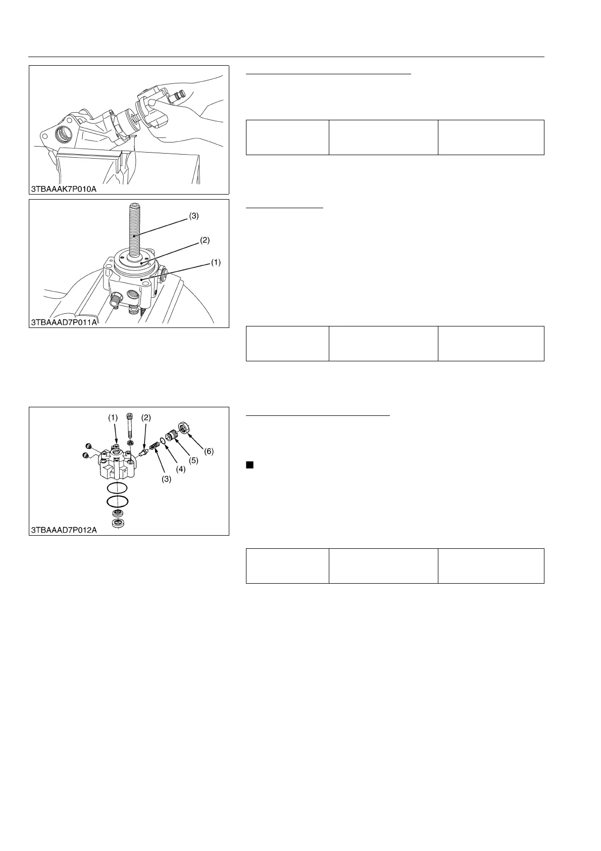
Disassembling Valve Housing
1. Loosen the lock nut (6) and remove the adjusting screw (5).
2. Remove the relief spring (3) and the relief valve poppet (2).
(When reassembling)
• Do not disassemble the relief valve needlessly, since it has
been factory-adjusted.
• If the relief valve is disassembled, replace the adjusting
screw with new one, and after reassembly, be sure to
adjust the setting pressure, then stake the adjusting screw
with a punch.
9Y1210436STS0019US0
Tightening torque
Valve housing mounting
hex. head screw
40 to 49 N·m
4.0 to 5.0 kgf·m
29 to 36 lbf·ft
Tightening torque Plug
8.9 to 10 N·m
0.90 to 1.1 kgf·m
6.5 to 7.9 lbf·ft
(1) Valve Housing
(2) Plug
(3) Worm Shaft
Tightening torque
Relief pressure adjusting
screw lock nut
49 to 78 N·m
5.0 to 8.0 kgf·m
37 to 57 lbf·ft
(1) Valve Housing
(2) Relief Valve Poppet
(3) Relief Spring
(4) O-ring
(5) Adjusting Screw
(6) Lock Nut