ELECTRICAL SYSTEM
B2420, WSM
9-S9
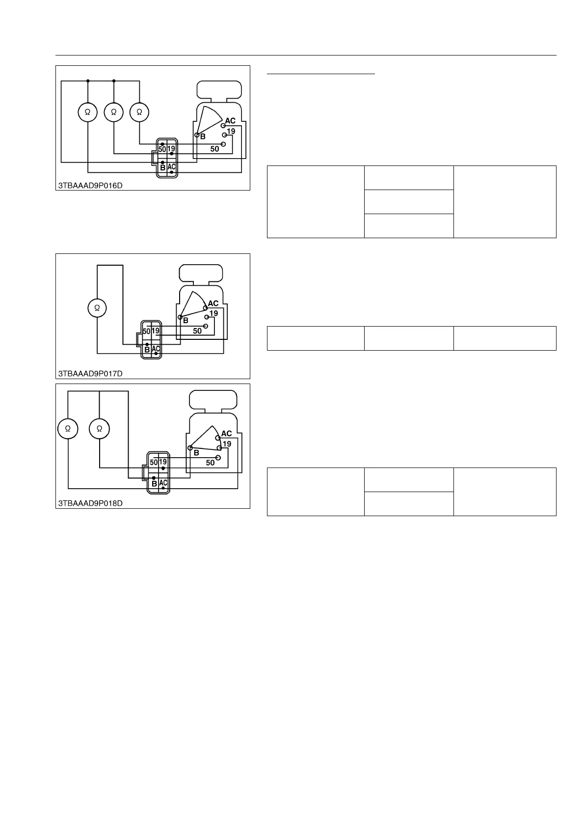
Main Switch Continuity
1) Main Switch Key at OFF Position
1. Set the main switch OFF position.
2. Measure the resistance with an ohmmeter across the B terminal
and the AC terminal, B terminal and 50 terminal, B terminal and
19 terminal.
3. If infinity is not indicated, the contacts of the main switch are
faulty.
9Y1210436ELS0028US0
2) Main Switch Key at ON Position
1. Set the main switch ON position.
2. Measure the resistance with an ohmmeter across the B terminal
and the AC terminal.
3. If 0 Ω is not indicated, the B - AC contact of the main switch are
faulty.
9Y1210436ELS0029US0
3) Main Switch Key at PREHEAT Position
1. Set and hold the main switch key at the PREHEAT position.
2. Measure the resistance with an ohmmeter across the B terminal
and the 19 terminal, and measure the resistance across the B
terminal and the AC terminal.
3. If 0 Ω is not indicated, these contacts of the main switch are
faulty.
9Y1210436ELS0030US0
Resistance
B terminal –
AC terminal
Infinity
B terminal –
50 terminal
B terminal –
19 terminal
Resistance
B terminal –
AC terminal
0 Ω
Resistance
B terminal –
19 terminal
0 Ω
B terminal –
AC terminal
 Loading...
